2
2
2-15
2-15
Technology > Original Exposure System > Controls > Image Processing
Technology > Original Exposure System > Controls > Image Processing
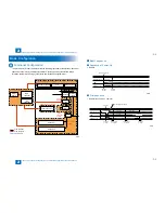
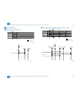
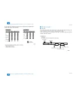
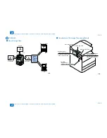
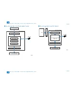
CMOS Sensor Drive
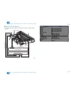
The CMOS sensor used in this machine is a 1-line linear image sensor consisting of 7488
photocells. After completion of photoelectric conversion in the lightreceiving block, the signals
are output to the AP circuit in the reader relay PCB in parallel for each channel (total four
channels) of the CMOS sensor array.
CMOS sensor 1
CMOS sensor 4
CMOS sensor 3
H
L L
H
H L
H
L H
H L
………
output
Light receiving block
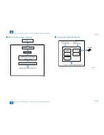
CMOS Sensor Output Gain Correction and Offset Correction
The analog video signals output from the CMOS sensor are corrected so that they will have
a specific gain level (gain correction), and the output voltages generated in the absence
of incident light are also corrected so that they it will have a specific offset level (offset
correction).
CMOS Sensor Output A/D Conversion
After completion of the above corrections, the analog video signals are converted to digital
signals corresponding to individual pixel voltage levels by the A/D converter.
●
●
●
F-2-28
F-2-28
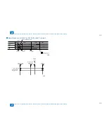
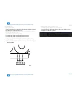
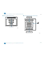
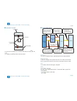
Shading Correction (Outline)
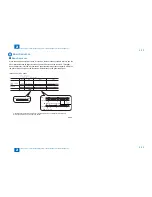
The CMOS sensor outputs are necessary even for the following reasons even when the
density of the original is uniform:
(1) Variation in sensitivity among CMOS sensor pixels
(2) Variation in light intensity of rod lens array
The machine performs shading correction to even out the CMOS sensor output.
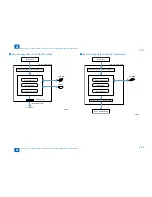
There are two types of shading correction: shading adjustment performed in the Service
mode and shading correction performed for each job.
Shading Adjustment
The machine measures the density of the standard white plate, and stores the measured
density data. It then processes the stored data to use it as the target value for shading
correction.
Shading Correction
The machine performs shading correction for each scan. It measures the density of the
standard white plate, and compares the measured value with the target value stored in the
shading correction circuit to use the difference between the two as the shading correction
value. The machine uses this shading correction value to correct the variation among CMOS
sensor pixels when scanning the original, thus evening out the image density level.
CMOS
sensor
output
Original density
Standard white plate
Characteristics
before correction
Target
value
Measurement
value
Characteristics
after correction
White
●
●
●
F-2-29
F-2-29
Содержание IMAGERUNNER 2530
Страница 1: ...9 8 7 6 5 4 3 2 1 imageRUNNER 2530 2525 2520 Series Service Manual...
Страница 4: ...Blank Page...
Страница 16: ...1 1 Product Overview Product Overview Product Lineup Feature Specifications Name of Parts...
Страница 111: ...3 3 Periodical Service Periodical Service Consumable Parts and Cleaning Parts...
Страница 159: ...5 5 Adjustment Adjustment Outline Adjustment when replacing parts Image position adjustment...
Страница 166: ...6 6 Troubleshooting Troubleshooting Upgrading Targets and Procedure...
Страница 171: ...7 7 Error Code Error Code Overview Error Code Jam Code Alarm Code...
Страница 186: ...8 8 Service Mode Service Mode Outline Details of Service Mode...
Страница 321: ...Service Tools General Circuit Diagram Appendix...

