9
9
9-20
9-20
Installation > Document Tray-J1 Installation Procedure > Installation Procedure > When installing with “USB Application 3-Port Interface Kit-A1” simultaneously
Installation > Document Tray-J1 Installation Procedure > Installation Procedure > When installing with “USB Application 3-Port Interface Kit-A1” simultaneously
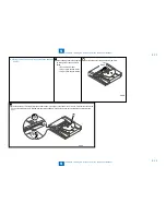
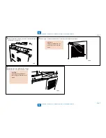
When installing with "USB Application 3-Port Interface Kit-A1" simultaneously
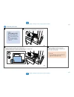
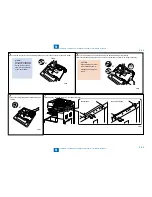
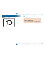
1) Tighten the 2 stepped screws (RS tightening; M4X18) to the USB Application 3-Port Interface Kit.
x2
F-9-39
F-9-39
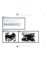
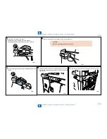
2) Hook the cut-off of the Document Tray (Reinforcing Plate) to the stepped screws tightened in the
Installation > Document Tray-J1 Installation Procedure > Installation Procedure > When installing with “USB Application 3-Port Interface Kit-A1” simultaneouslystep 1).
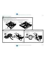
Stepped Screw
Cut-off
F-9-40
F-9-40
■
Содержание IMAGERUNNER 2530
Страница 1: ...9 8 7 6 5 4 3 2 1 imageRUNNER 2530 2525 2520 Series Service Manual...
Страница 4: ...Blank Page...
Страница 16: ...1 1 Product Overview Product Overview Product Lineup Feature Specifications Name of Parts...
Страница 111: ...3 3 Periodical Service Periodical Service Consumable Parts and Cleaning Parts...
Страница 159: ...5 5 Adjustment Adjustment Outline Adjustment when replacing parts Image position adjustment...
Страница 166: ...6 6 Troubleshooting Troubleshooting Upgrading Targets and Procedure...
Страница 171: ...7 7 Error Code Error Code Overview Error Code Jam Code Alarm Code...
Страница 186: ...8 8 Service Mode Service Mode Outline Details of Service Mode...
Страница 321: ...Service Tools General Circuit Diagram Appendix...

