8
8
8-51
8-51
Service Mode > Details of Service Mode > #TEST MODE > Details
Service Mode > Details of Service Mode > #TEST MODE > Details
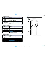
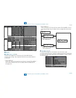
Card reader test <6-3: NCR sts>
Press numeric keypad key 3 on the FACULTY menu to select the card reader test. In this test,
verify the successful operations of the card reader.
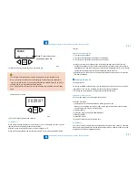
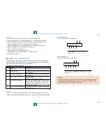
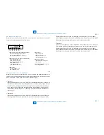
NCR Sts
:
12345678
DPT MGN OK RDY 1234
[1] Card reader and card availability indication
Card available: Eight-digit card ID
No card: Card None
No card reader available: NCR None
[2] Card type and card reader status indication
DPT: Department card
PRC: Unit pricing card
MAX: Upper limit setting card
ERS: Erased card
SRV: Service card
(No indication): No card
[3] Card type
MGN: Magnetic card
OPT: Optical card
[1]
[2]
[3] [4] [5]
[6]
Press numeric keypad key 3
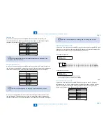
[4] Can status
OK: Normal scan
ERR: Scan error
NG: Nonstandard error
(No indication): No card
[5] Equipment status
IN: Initialization in progress
RDY: Ready
[6] Card reader version indication
Four-digit number
Line signal reception test <6-9: LINE DETECT>
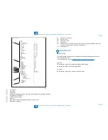
Press numeric keypad key 9 on the FACULTY menu to select the line signal reception test. In
this test, verify the successful operations of the NCU signal sensor and the frequency counter.
Menu 1 detects the CI state, while menu 3 detects the CNG signal.
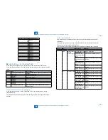
Test menu 1
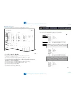
Press numeric keypad key 1 on the LINE DETECT menu to select test menu 1. When CI is
detected on the telephone line connection terminal, the touch panel (LCD) display changes
from OFF to ON, indicating the received frequency. The touch panel (LCD) also displays
the on-hook or off-hook state of an external telephone set as detected. The touch panel
(LCD) displays, from left to right, CI, CI frequency, hook port and FC with indications of 1:
ON and 0:OFF.
Test menu 2
Press numeric keypad key 2 on the LINE DETECT menu to select test menu 2. When the
CNG signal is detected on the telephone line connection terminal, the touch panel (LCD)
•
•
F-8-15
display changes from OFF to ON, indicating the received frequency. The touch panel
(LCD) displays the status of CML, CNG and FED detection, from left to right, with ON/OFF
indications. Numeric keypad key 2 turns on the CML relay to detect CNG.
Test menu 3
Press numeric keypad key 3 on the LINE DETECT menu to select test menu 3. When the
CNG signal is detected on the telephone line connection terminal, the touch panel (LCD)
display changes from OFF to ON, indicating the received frequency. The touch panel
(LCD) displays the status of CML, CNG and FED detection, from left to right, with ON/OFF
indications. Numeric keypad key 3 turns off the CML relay to detect CNG.
•
Содержание IMAGERUNNER 2530
Страница 1: ...9 8 7 6 5 4 3 2 1 imageRUNNER 2530 2525 2520 Series Service Manual...
Страница 4: ...Blank Page...
Страница 16: ...1 1 Product Overview Product Overview Product Lineup Feature Specifications Name of Parts...
Страница 111: ...3 3 Periodical Service Periodical Service Consumable Parts and Cleaning Parts...
Страница 159: ...5 5 Adjustment Adjustment Outline Adjustment when replacing parts Image position adjustment...
Страница 166: ...6 6 Troubleshooting Troubleshooting Upgrading Targets and Procedure...
Страница 171: ...7 7 Error Code Error Code Overview Error Code Jam Code Alarm Code...
Страница 186: ...8 8 Service Mode Service Mode Outline Details of Service Mode...
Страница 321: ...Service Tools General Circuit Diagram Appendix...

