9
9
32
32
Installation > Serial Interface Kit-J2 Installation Procedure > Installation Procedure
Installation > Serial Interface Kit-J2 Installation Procedure > Installation Procedure
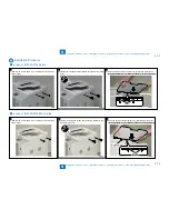
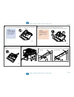
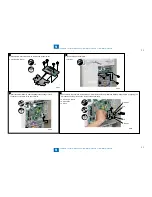
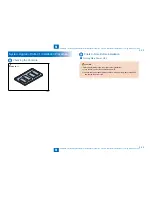
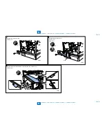
4) Install the RS Conversion PCB on the RS232C Support Plate.
4 Screws (TP: M3x6)
•
x4
F-9-71
F-9-71
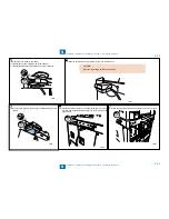
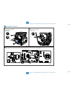
5) Remove the Controller plate.
3 Screws
•
x3
F-9-72
F-9-72
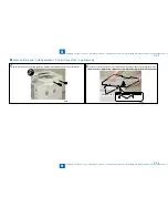
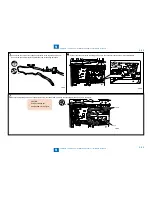
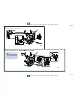
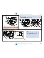
6) Insert the CV-Serial Relay Cable included in the package to the 2
connectors on the PCB of the host machine.
x2
F-9-73
F-9-73
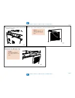
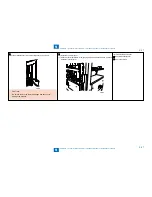
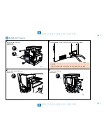
7) Connect the RS Conversion PCB and the CV-Serial Relay Cable, and install the RS232C Support Plate by aligning the
2 Protrusions on the plate with the Holes on the host machin.
2 Screws (TP: M3x6)
2 Protrusions
2 Holes
•
•
•
x2
Protrusion
Protrusion
Hole
Hole
F-9-74
F-9-74
Содержание IMAGERUNNER 2530
Страница 1: ...9 8 7 6 5 4 3 2 1 imageRUNNER 2530 2525 2520 Series Service Manual...
Страница 4: ...Blank Page...
Страница 16: ...1 1 Product Overview Product Overview Product Lineup Feature Specifications Name of Parts...
Страница 111: ...3 3 Periodical Service Periodical Service Consumable Parts and Cleaning Parts...
Страница 159: ...5 5 Adjustment Adjustment Outline Adjustment when replacing parts Image position adjustment...
Страница 166: ...6 6 Troubleshooting Troubleshooting Upgrading Targets and Procedure...
Страница 171: ...7 7 Error Code Error Code Overview Error Code Jam Code Alarm Code...
Страница 186: ...8 8 Service Mode Service Mode Outline Details of Service Mode...
Страница 321: ...Service Tools General Circuit Diagram Appendix...


