4
4
4-42
4-42
Parts Replacement and Cleaning > PCB > Removing the RAM PCB > Replacement Procedure
Parts Replacement and Cleaning > PCB > Removing the RAM PCB > Replacement Procedure
Removing the RAM PCB
Replacement Procedure
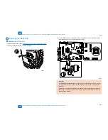
1) Remove the rear cover (right). (
"Removing the Rear Cover (Right)"(page 4-20)..
)
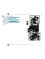
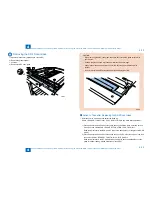
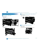
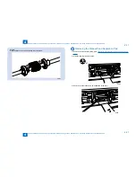
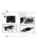
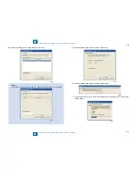
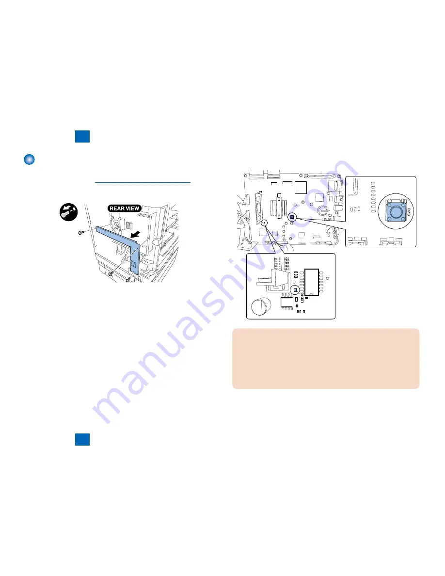
2) Remove the controller plate. (Remove 3 screws.)
x3
■
F-4-95
F-4-95
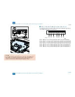
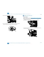
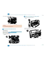
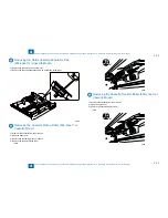
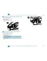
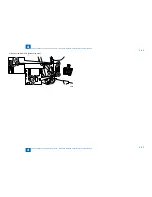
3) For the model with a FAX and SEND function, press the SW3 on the main controller to
check that LED10 goes out. (Secondary power cutoff)
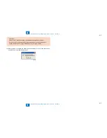
CAUTION:
The ADRAM is powered from the secondary battery unit to back up the image memory
even after the main power switch is turned OFF and the power plug is removed from
the outlet.
If the SW3 on the main controller PCB is pressed with the image backed up, the entire
data stored in the memory is cleared. Be sure to output the data stored in the memory
before pressing the SW3.
F-4-96
F-4-96
Содержание IMAGERUNNER 2530
Страница 1: ...9 8 7 6 5 4 3 2 1 imageRUNNER 2530 2525 2520 Series Service Manual...
Страница 4: ...Blank Page...
Страница 16: ...1 1 Product Overview Product Overview Product Lineup Feature Specifications Name of Parts...
Страница 111: ...3 3 Periodical Service Periodical Service Consumable Parts and Cleaning Parts...
Страница 159: ...5 5 Adjustment Adjustment Outline Adjustment when replacing parts Image position adjustment...
Страница 166: ...6 6 Troubleshooting Troubleshooting Upgrading Targets and Procedure...
Страница 171: ...7 7 Error Code Error Code Overview Error Code Jam Code Alarm Code...
Страница 186: ...8 8 Service Mode Service Mode Outline Details of Service Mode...
Страница 321: ...Service Tools General Circuit Diagram Appendix...

