2
2
2-75
2-75
Technology > Embedded RDS > E-RDS Setup > Steps to E-RDS Settings
Technology > Embedded RDS > E-RDS Setup > Steps to E-RDS Settings
Steps to E-RDS Settings
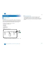
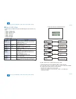
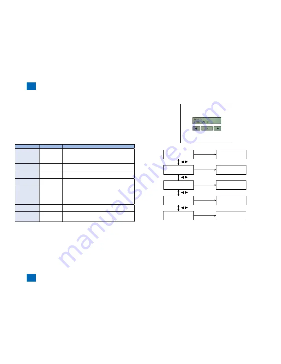
Locations of the user interface which performs E-RDS Settings from the servicemode is as
follows.
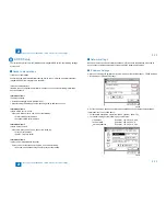
#E-RDS > E-RDS SWITCH
#E-RDS > RGW-ADDRESS
#E-RDS > RGW-PORT
#E-RDS > COM-TEST
#E-RDS > COM-LOG
#CLEAR > ERDS-DAT
#CLEAR > CA-KEY
Item
String format
Description
#E-RDS >
E-RDS SWITCH
1 byte
0: Disable/ 1:Enable e-Maintenance/ imageWARE Remote
system to send device information, counter data, error
statuses to the UGW.
Default value is 0 (not in use)
#E-RDS >
RGW-ADDRESS
129 bytes
(SJIS not allowed)
URL of UGW (default)
:
https://a01.ugwdevice.net/ugw/agentif010
#E-RDS >
RGW-PORT
2 bytes
The UGW Port Number by default : 443
Validation: 1~ 65,535
#E-RDS >
COM-TEST
Perform Communication test with UGW and set "OK"/ "NG"
as the result
#E-RDS >
COM-LOG
Detailed communication log displays the last 5 error
information, consisting of data, error code, and error
reasons up to now
Max 5 latest loggings retained
Max 128 characters for Error information.
#CLEAR >
ERDS-DAT
Reset E-RDS settings
#CLEAR >
CA-KEY
After executing #CLEAR > CA-KEY, if the power is turned
OFF and then ON, CA certificate file is automatically
installed.
■
•
•
•
•
•
•
•
T-2-43
T-2-43
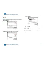
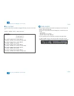
The example of the service mode indication screen
#E-RDS
E-RDS SWITCH
001
1
OK Key
Key
#E-RDS
#E-RDS
RGW-ADDRESS
https://a01.ugwdevi..
OK Key
Key
#RGW-ADDRESS :A
#E-RDS
RGW-PORT
001
443
OK Key
Key
#RGW-PORT
#E-RDS
COM-TEST
COM-TEST OK
OK Key
Key
#E-RDS
#E-RDS
COM-LOG
2009 03/24 11:56
OK Key
No:1 Ecode:870F2052
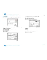
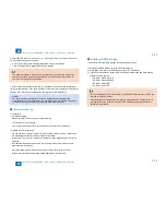
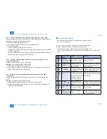
Hereafter, the procedure of enabling E-RDS application is shown.
a. Enter servicemode and select #CLEAR > ERDS-DAT, and then touch [OK].
After executing the procedure a. (#CLEAR > ERDS-DAT), install or delete the CA certificate
file as necessary, and then turn OFF and then ON the power.
Installation of CA certificate file: Use SST to install.
Deletion of CA certificate file: Execute #CLEAR > CA-KEY. (CA certificate file is
automatically installed.)
•
•
F-2-108
F-2-108
F-2-109
F-2-109
Содержание IMAGERUNNER 2530
Страница 1: ...9 8 7 6 5 4 3 2 1 imageRUNNER 2530 2525 2520 Series Service Manual...
Страница 4: ...Blank Page...
Страница 16: ...1 1 Product Overview Product Overview Product Lineup Feature Specifications Name of Parts...
Страница 111: ...3 3 Periodical Service Periodical Service Consumable Parts and Cleaning Parts...
Страница 159: ...5 5 Adjustment Adjustment Outline Adjustment when replacing parts Image position adjustment...
Страница 166: ...6 6 Troubleshooting Troubleshooting Upgrading Targets and Procedure...
Страница 171: ...7 7 Error Code Error Code Overview Error Code Jam Code Alarm Code...
Страница 186: ...8 8 Service Mode Service Mode Outline Details of Service Mode...
Страница 321: ...Service Tools General Circuit Diagram Appendix...


