9
9
9-61
9-61
Installation > Cassette Heater Unit 37 > Installation Procedure > In case of Options(Cassette Module)
Installation > Cassette Heater Unit 37 > Installation Procedure > In case of Options(Cassette Module)
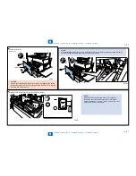
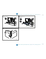
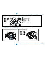
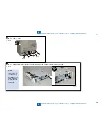
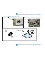
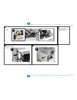
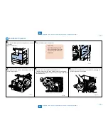
3) Remove the Lower rear cover.
1 Screw
2 Hooks
•
•
Hook
x2
Hook
F-9-131
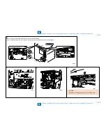
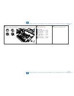
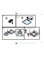
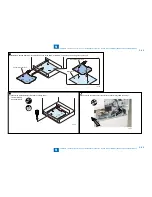
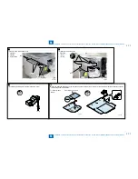
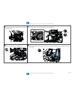
4) Remove the heater connector plate at rear side of the Cassette Module. (The removed heater connector plate will not be used.)
1 Screw
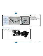
MEMO:
When performing
this procedure, it
is not necessary to
remove the main
body. However, the
figure shows the
picture without the
main body to
show easily.
•
F-9-132
Содержание IMAGERUNNER 2530
Страница 1: ...9 8 7 6 5 4 3 2 1 imageRUNNER 2530 2525 2520 Series Service Manual...
Страница 4: ...Blank Page...
Страница 16: ...1 1 Product Overview Product Overview Product Lineup Feature Specifications Name of Parts...
Страница 111: ...3 3 Periodical Service Periodical Service Consumable Parts and Cleaning Parts...
Страница 159: ...5 5 Adjustment Adjustment Outline Adjustment when replacing parts Image position adjustment...
Страница 166: ...6 6 Troubleshooting Troubleshooting Upgrading Targets and Procedure...
Страница 171: ...7 7 Error Code Error Code Overview Error Code Jam Code Alarm Code...
Страница 186: ...8 8 Service Mode Service Mode Outline Details of Service Mode...
Страница 321: ...Service Tools General Circuit Diagram Appendix...

