Solution 6000
Installation Manual
Installing the Hardware
2-7
Bosch Security Systems 07/14 BLCC610I
In version 2.14, this has been corrected so that the
RED status led will turn off when the user turns off the
area via the keypad regardless of any trouble events
being present.
K E YPA D & R E A D E R S S E T U P
The control panel can have a maximum of 16 keypads
and/or readers connected via the LAN terminals. Each
keypad or reader must be set to a unique address before
they will operate.
Each keypad or reader needs to be assigned to a home
area via MENU 6-1-3. This sets the area the keypad or
reader will display and control by default. Keypads and
readers can be locked to a home area or allowed to roam
or move between areas. At factory default, the home area
is factory default to operate Area 1.
Set each keypad or reader address using "Table 7: DIP
Switch Address Settings" on page 2-7 and "Table 8:
Rotary Switch Address Settings" on page 2-7 as a guide.
i
Note
Only 1 keypad can be assigned to each address. All
keypads are supplied from the factory set to address
1. (OFF-OFF-OFF-OFF).
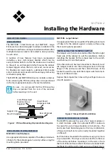
D I P S W I TC H A D D R E S S S E L E C T
4
Figure 10: Keypad DIP Switch Address Settings
DIP Switch Address Settings
Keypad/Reader N
o
S1
S2
S3
S4
1
Off
Off
Off
Off
2
On
Off
Off
Off
3
Off
On
Off
Off
4
On
On
Off
Off
5
Off
Off
On
Off
6
On
Off
On
Off
7
Off
On
On
Off
8
On
On
On
Off
9
Off
Off
Off
On
10
On
Off
Off
On
11
Off
On
Off
On
12
On
On
Off
On
13
Off
Off
On
On
14
On
Off
On
On
15
Off
On
On
On
16
On
On
On
On
Table 7: DIP Switch Address Settings
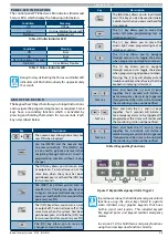
R OTA RY S W I TC H A D D R E S S S E L E C T
Keypads and readers fitted to the system must be as-
signed a unique address on the LAN. Some keypads and
readers include a rotary address switch for quick selec-
tion.
The following table shows how to set the address set-
ting for each keypad and reader, as well as the number of
devices the panel can support.
Rotary Switch Address Settings
Address Number
Keypad/Reader N
o
1
1
2
2
3
3
4
4
5
5
6
6
7
7
8
8
9
9
10
10
11
11
12
12
13
13
14
14
15
15
16
16
Table 8: Rotary Switch Address Settings
Figure 11: Rotary Swich Address Settings
Содержание SOLUTION 6000
Страница 1: ...Solution 6000 Security System Installation Guide EN Security Systems ...
Страница 42: ...Solution 6000 Installation Manual Programming Overview 4 12 Bosch Security Systems 07 14 BLCC610I ...
Страница 82: ...Solution 6000 Installation Manual Input Programming 7 16 Bosch Security Systems 07 14 BLCC610I ...


