Solution 6000
Installation Manual
Input Programming
7-9
Bosch Security Systems 07/14 BLCC610I
Inputs > Zone Properties >
Door Assignment
MENU 3-1-5
0
0
00 - No Door Assignment
01 - Door 1 Name
09 - Door 9 Name
02 - Door 2 Name
10 - Door 10 Name
03 - Door 3 Name
11 - Door 11 Name
04 - Door 4 Name
12 - Door 12 Name
05 - Door 5 Name
13 - Door 13 Name
06 - Door 6 Name
14 - Door 14 Name
07 - Door 7 Name
15 - Door 15 Name
08 - Door 8 Name
16 - Door 16 Name
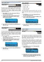
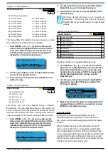
This menu allows the installer to assign a zone to a single
door. There are 16 different doors available.
1)
Press [MENU] + [3] + [1] + [5] and use the up and
down arrows to highlight the Zone in the list then
press [OK]. Alternatively, you can enter the zone
number directly and press [OK]. The keypad will
display the current door assignment.
Door Assignment Zn1
00 - No Door Assignment
Press
0-9 OK to SAVE
2)
Use the up and down arrows to select the door that
you want to assign the zone to.
3)
Press [OK] to save and exit or press [MENU] to exit
without saving.
Inputs > Zone Properties >
Report Route
MENU 3-1-6
00 - Log Events Only
0
1
01 - Dest 1 + Log
02 - Dest 2 + Log
03 - Dest 1 & 2 + Log
04 - Dest 2 If 1 Fails
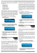
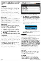
This menu sets the Zone Report Route or Report
Destination for each individual zone in the system. All
events such as alarms and troubles for each zone will be
reported according to this menu setting. Each zone can
only be assigned to one report route from the list above.
1)
Press [MENU] + [3] + [1] + [6] and use the up and
down arrows to highlight the Zone in the list then
press [OK]. Alternatively, you can enter the zone
number directly and press [OK]. The keypad will
display the current Zone Report Route.
Report Route Zn1
01 - Dest 1 + Log
Press
0-9 OK to SAVE
2)
Use the up and down arrows to select the Report
Route that you want to assign the zone to.
3)
Press [OK] to save and exit or press [MENU] to exit
without saving.
i
Note
At factory default all Zones are set to report to
Destination 1 and the System Log. See the Zone
Default Table for more information on Zone default
settings.
Inputs > Zone Properties >
Report Options
MENU 3-1-7
1
Lockout Dialler
Y
2
Report Alarm
Y
3
Report Troubles
Y
4
Report Bypass
Y
5
Reserved
N
6
Reserved
N
7
Report Restores
Y
8
Delay Reporting
N
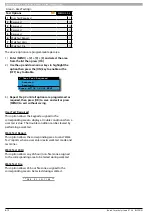
The above options are programmable per zone.
1)
Press [MENU] + [3] + [1] + [7] and use the up and
down arrows to highlight the Zone in the list then
press [OK]. Alternatively, you can enter the zone
number directly and press [OK]. The keypad will
display the Report Options for the currently
selected zone.
2)
Use the up and down arrow keys to highlight the
option then press the [ON] key to enable or the
[OFF] key to disable.
Lockout Dialler
Report Alarm
Report Troubles
Press
OK ON OFF MENU
3)
Repeat Step 2 until all options are programmed as
required, then press [OK] to save and exit or press
[MENU] to exit without saving.
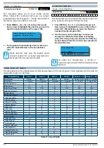
Lockout Dialler
Setting this option will enable Dialler Lockout
functionality for the respective zone(s). All zones in
the system can be individually programmed for Dialler
Lockout.
When enabled the zone will be allowed to transmit
alarm reports each time it is triggered provided that
the Swinger Dialler count has not been reached. If the
zone is triggered and the Swinger Dialler count has been
reached then the zone will become locked out and no
further reports will be sent for that zone. Dialler lockout
will be reset on the next arming cycle.
Содержание SOLUTION 6000
Страница 1: ...Solution 6000 Security System Installation Guide EN Security Systems ...
Страница 42: ...Solution 6000 Installation Manual Programming Overview 4 12 Bosch Security Systems 07 14 BLCC610I ...
Страница 82: ...Solution 6000 Installation Manual Input Programming 7 16 Bosch Security Systems 07 14 BLCC610I ...


