4-38
Protection and Control
BE1-951
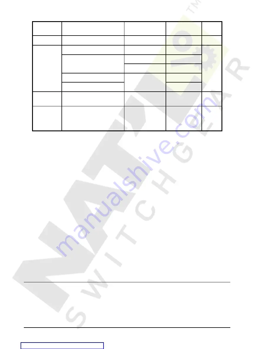
Table 4-30. Operational Underfrequency and Overfrequency Settings
Setting
Range
Increment
Unit of
Measure
Default
Pickup
40 to 70, 0 = disabled
0.01
hertz
0
Time Delay
0 to 999 milliseconds
1
milliseconds
0
0.0 to 600 seconds
0.1 for 0.1 to 9.9
seconds
1.0 for 10 to 600
seconds
0 to 36,000 cycles (60 Hz)
9
cycles
0 to 30,000 cycles (50 Hz)
Mode
O = overfrequency
U = underfrequency
N/A
N/A
0
Inhibit Level
15 to 300
0 = disabled(functions
enabled for all voltage
levels)
0.1 (for 0.1 - 99.9)
1.0 (for 100 - 300)
secondary
volts
#
40.0
9
Time delays less than 10 cycles can be entered to the nearest 0.1 cycle from the front panel
HMI. All time delays can be entered to the nearest 0.01 cycle from the ASCII command interface.
Time delays entered in cycles are converted to milliseconds or seconds. Increment precision after
conversion is limited to that appropriate for each of those units of measure.
#Phase-to-phase and phase-to-neutral settings depend on the VTP and VTX connection settings.
S<g>-81 Command
Purpose:
Read or set the 81 pickup level, time delay, and underfrequency/overfrequency mode.
Syntax:
S<g>-<x>81[=<Pickup>,<Time Dial>,<Mode>]
Comments: g = setting group 0, 1, 2, or 3. Use # as a wildcard to read or change all groups.
x = 1 for 181, 2 for 281, 3 for 381, 4 for 481, 5 for 581, or no entry for 81.
See Table 4-28 for S<g>-81 settings information.
S<g>-81 Command Example
1.
In setting group 0, set the 81 element for underfrequency protection with a set-point of 59.5 hertz
and a time delay of 2 seconds.
>S0-81=59.5,2,U
S<g>-81INH Command
Purpose:
Read or set the 81 undervoltage inhibit level.
Syntax:
S<g>-81INH[=<Inhibit Level>]
Comments:
g = setting group 0, 1, 2, or 3. Use # as a wildcard to read or change all groups. See
Table 4-28 for S<g>-81 settings information.
S<g>-81INH Command Example
1.
Set the undervoltage inhibit for all setting groups at 100 volts.
>S#-81INH=100
RECLOSING
The BE1-951 reclosing function provides up to four reclosing attempts that can be initiated by a protective
trip or by one of the contact sensing inputs. The recloser allows supervisory control and coordination of
tripping and reclosing with other system devices. Any of the four recloser shots can be used to select a
different setting group when the appropriate shot is reached in a reclosing sequence. This change in setting
groups allows changing protection coordination during the reclosing sequence. For example, you could have
a fast 51 curve on the first two trips in the reclosing sequence and then switch to a new group on the second
Содержание BE1-951
Страница 157: ...BESTlogic Programmable Logic BE1 951 7 2 Figure 7 1 BESTlogic Function Blocks Courtesy of NationalSwitchgear com...
Страница 238: ...BE1 951 Human Machine Interface 10 5 Figure 10 5 Metering Menu Branch Structure Courtesy of NationalSwitchgear com...
Страница 239: ...10 6 Human Machine Interface BE1 951 Figure 10 6 Reports Menu Branch Structure Courtesy of NationalSwitchgear com...
Страница 270: ...12 2 Installation BE1 951 Figure 12 1 BE1 951 S1 Case Dimensions Courtesy of NationalSwitchgear com...
Страница 274: ...12 6 Installation BE1 951 Figure 12 5 BE1 951 H1 Case Dimensions Courtesy of NationalSwitchgear com...
Страница 283: ...BE1 951 Installation 12 15 Figure 12 16 Typical AC Connections Courtesy of NationalSwitchgear com...
Страница 394: ...A 18 Appendix BE1 951 Figure A 14 Time Characteristic Curve B Very Inverse 99 1376 Courtesy of NationalSwitchgear com...
Страница 396: ...A 20 Appendix BE1 951 Figure A 16 Time Characteristic Curve G Long Inverse 99 1622 Courtesy of NationalSwitchgear com...
Страница 397: ...BE1 951 Appendix A 21 Figure A 17 46 Time Characteristic Curve Courtesy of NationalSwitchgear com...


