BE1-951
Protection and Control
4-35
If the target is enabled for the element, the target reporting function will record a target when the protective
function trip output is TRUE and the fault recording function trip logic expression is TRUE. See Section 6,
Reporting and Alarm Functions, Fault Reporting Functions for more information about target reporting.
BESTlogic Settings for the Directional Overpower Element
Logic settings for the 32 function are made using the SL-32 (settings logic-power) command. The settings
of this command determine whether the element is enabled or disabled. The SL command also provides
blocking control as determined by the logic expression assigned to the BLK input. See Table 4-27 for
directional overpower logic settings.
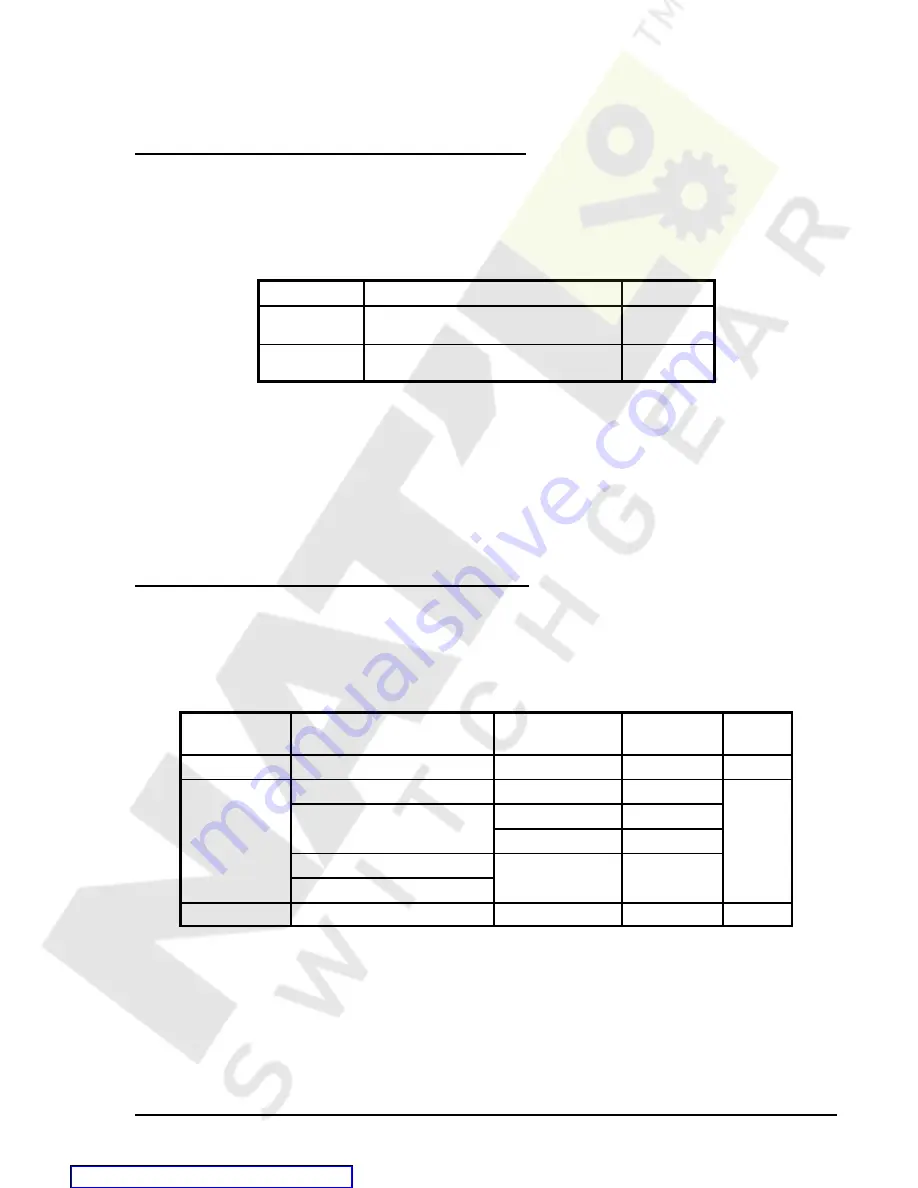
Table 4-27. Directional Overpower Logic settings
Function
Range/Purpose
Default
mode
0=Disable
1=enable
1
BLK logic
Logic expression that disables
function when true
0
SL-32 Command
Purpose:
Read or set logic for the Directional Overpower element
Syntax:
SL-32[=<mode>,<BLK logic>]
Comments:
Refer to Table 4-27 for settings definitions
SL-32 Command Example
Enable the 32 when IN3 is energized (= Block 32 when IN3 open):
>SL-32=1,/IN3
Operating Settings for the Directional Overpower Elements
Operating settings for the 32 elements consist of the pickup in secondary three-phase watts, time delay, and
forward/reverse mode setting. Settings are made using the S<g>-32 command. These settings can also be
viewed or changed at the front panel HMI using screen 5.x.4.1 where x equals 1 for setting group 0, and 2
for setting group 1. See Table 4-28 for the Directional Over Power Function Settings.
Table 4-28. Directional Over Power Function Settings
Setting
Range
Increment
Unit of
measure
Default
pu (pickup)
0=disabled, 1-6000
0.1 / 1
sec. watts
0
td
(time delay)
0 to 999 milliseconds
1
milliseconds
0
0.0 to 600 seconds
0.1 for 0.1 to 9.9
seconds
1.0 for 10 to 600
seconds
0 to 36,000 cycles (60 Hz)
7
cycles
0 to 30,000 cycles (50 Hz)
mode
F=Forward, R=Reverse
N/A
N/A
R
7
Time delays less than 10 cycles can be entered to the nearest 0.1 cycle from the HMI. All time
delays can be entered to the nearest 0.01 cycle from the ASCII command interface. Time delays
entered in cycles are converted to milliseconds or seconds. Increment precision after conversion
is limited to that appropriate for each of those units of measure.
Содержание BE1-951
Страница 157: ...BESTlogic Programmable Logic BE1 951 7 2 Figure 7 1 BESTlogic Function Blocks Courtesy of NationalSwitchgear com...
Страница 238: ...BE1 951 Human Machine Interface 10 5 Figure 10 5 Metering Menu Branch Structure Courtesy of NationalSwitchgear com...
Страница 239: ...10 6 Human Machine Interface BE1 951 Figure 10 6 Reports Menu Branch Structure Courtesy of NationalSwitchgear com...
Страница 270: ...12 2 Installation BE1 951 Figure 12 1 BE1 951 S1 Case Dimensions Courtesy of NationalSwitchgear com...
Страница 274: ...12 6 Installation BE1 951 Figure 12 5 BE1 951 H1 Case Dimensions Courtesy of NationalSwitchgear com...
Страница 283: ...BE1 951 Installation 12 15 Figure 12 16 Typical AC Connections Courtesy of NationalSwitchgear com...
Страница 394: ...A 18 Appendix BE1 951 Figure A 14 Time Characteristic Curve B Very Inverse 99 1376 Courtesy of NationalSwitchgear com...
Страница 396: ...A 20 Appendix BE1 951 Figure A 16 Time Characteristic Curve G Long Inverse 99 1622 Courtesy of NationalSwitchgear com...
Страница 397: ...BE1 951 Appendix A 21 Figure A 17 46 Time Characteristic Curve Courtesy of NationalSwitchgear com...


