BE1-951
Protection and Control
4-27
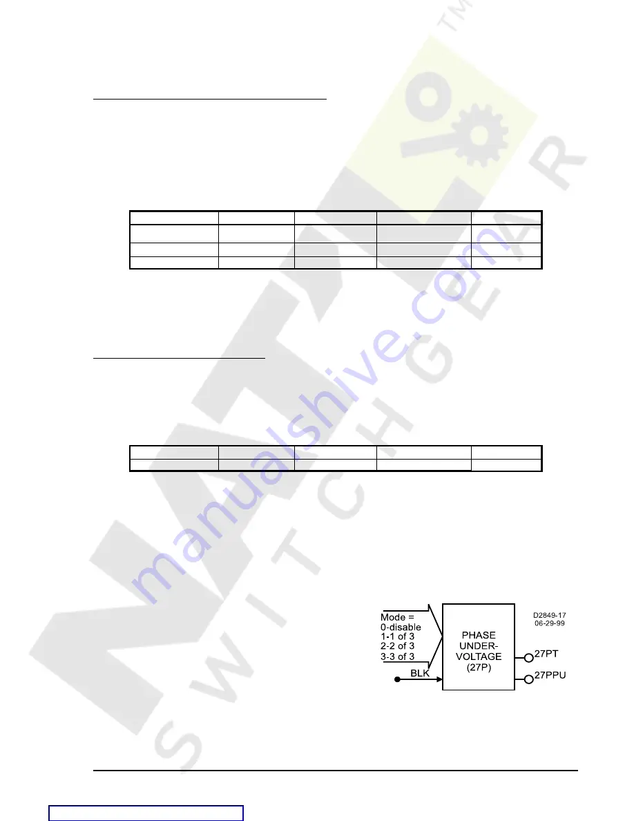
Figure 4-15. 27 Element
SL-24 Command Example
1.
Enable Volts/Hz protection but block when VO13 is low
SL-24=1,/VO13
Operating Settings for the Volts Per Hertz Element
Operating settings for the 24 function consist of a pickup setting, a trip time dial, and a reset time dial. A
pickup of 0 disables the element. Unit of measure is secondary Sec VPP/Hz or VPN/Hz and depends on the
SG-VTP setting. For more information, refer to Section 3,
Input and Output Functions, Voltage Inputs.
Settings are made using the S<g>-24 command. These settings can also be viewed or changed at the front
panel HMI using screen 5.x.1.1 where x equals 1 for setting group 0, 2 for setting group 1, 3 for setting group
2, and 4 for setting group 3. Table 4-18 lists the volts per hertz operating settings.
Table 4-18. Volts Per Hertz Function Operating Settings
Setting
Range
Increment
Unit of measure
Default
Pickup
0.5-6
0.1
sec. V/Hz
0
Trip Time Dial
0-9.9
0.1
N/A
0
Reset Time Dial
0-9.9
0.1
NA
0
S<g>-24 Command
Purpose:
Read or set the Volts Per Hertz pickup level and time dials.
Syntax:
S<g>-24[=<Pickup>,<Trip Time Dial>,<Reset Time Dial>]
Comments: g = setting group 0, 1, 2, or 3. Refer to Table 4-18 for S<g>-24 setting information.
Volts Per Hertz Programmable Alarm
The Volts Per Hertz function also has a settable alarm feature. If the Volts Per Hertz level reaches a settable
percentage of the pickup level (0-120%), a programmable alarm bit is set. See Section 6,
Reporting and
Alarm Functions for more information. The setting for the alarm is via the SA-24 command. Table 4-19 lists
the volts per hertz programmable alarm settings. Volts per hertz functions are also settable via HMI screen
5.3.1.
Table 4-19. Volts Per Hertz Function Programmable Alarm Settings
Setting
Range
Increment
Unit of measure
Default
Alarm Level
0-120
1
% of pickup level
0
SA-24 Command
Purpose:
Read or set logic for the Volts Per Hertz element
Syntax:
SA-24[=<Alarm Level>]
Comments: Refer to table 4-19 for settings information.
27P/59P Phase Undervoltage and Overvoltage Protection
Figure 4-15 illustrates the inputs and outputs of the phase undervoltage (27P) element. The phase over-
voltage (59P) element is identical in configuration.
Each element has two logic outputs: pickup and trip. When
the monitored voltage decreases below the undervoltage
pickup setting (27P) or increases above the overvoltage
pickup setting (59P), the pickup output becomes TRUE and
the element starts timing toward a trip. The trip output
becomes TRUE when the element timer times out.
The Block (BLK) input is used to disable protection. A
BESTlogic expression defines how the BLK input functions.
When this expression is TRUE, the element is disabled by
forcing the outputs to logic 0 and resetting the timer. This
feature functions in a similar way to the torque control contact of an electromechanical relay.
Содержание BE1-951
Страница 157: ...BESTlogic Programmable Logic BE1 951 7 2 Figure 7 1 BESTlogic Function Blocks Courtesy of NationalSwitchgear com...
Страница 238: ...BE1 951 Human Machine Interface 10 5 Figure 10 5 Metering Menu Branch Structure Courtesy of NationalSwitchgear com...
Страница 239: ...10 6 Human Machine Interface BE1 951 Figure 10 6 Reports Menu Branch Structure Courtesy of NationalSwitchgear com...
Страница 270: ...12 2 Installation BE1 951 Figure 12 1 BE1 951 S1 Case Dimensions Courtesy of NationalSwitchgear com...
Страница 274: ...12 6 Installation BE1 951 Figure 12 5 BE1 951 H1 Case Dimensions Courtesy of NationalSwitchgear com...
Страница 283: ...BE1 951 Installation 12 15 Figure 12 16 Typical AC Connections Courtesy of NationalSwitchgear com...
Страница 394: ...A 18 Appendix BE1 951 Figure A 14 Time Characteristic Curve B Very Inverse 99 1376 Courtesy of NationalSwitchgear com...
Страница 396: ...A 20 Appendix BE1 951 Figure A 16 Time Characteristic Curve G Long Inverse 99 1622 Courtesy of NationalSwitchgear com...
Страница 397: ...BE1 951 Appendix A 21 Figure A 17 46 Time Characteristic Curve Courtesy of NationalSwitchgear com...


