180
8. Repeat steps 2-4 until all desired Cameras have been setup. Up to 7 Cameras can be
configured, matching the number of camera inputs on the AVH21’s.
To exit setup, press the
Exit Button [oval 17]
. To continue Zone Setup, position the cursor next
to
BACK TO ZONE SETUP
and press the
Set Button [oval 18]
.
ZONE SETUP PAGE 1
will
appear.
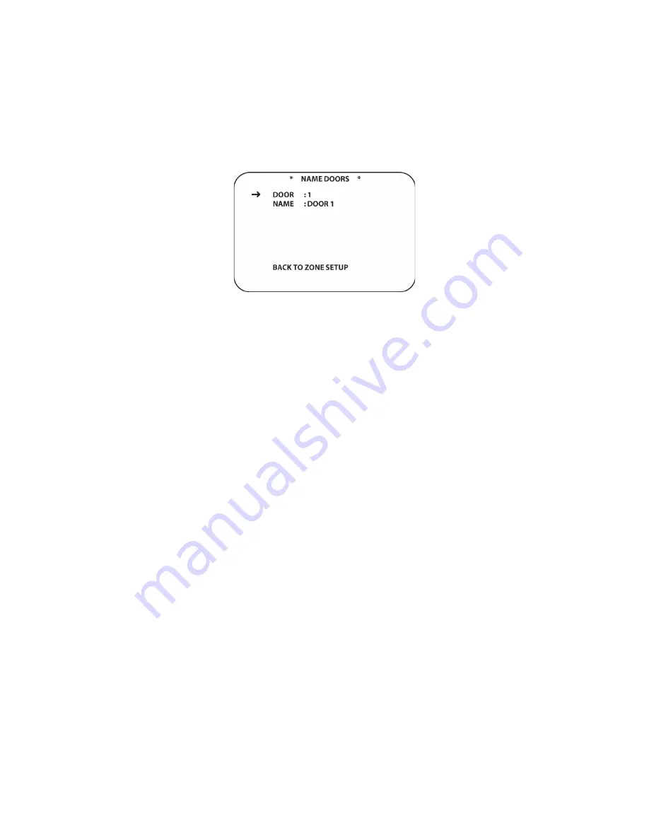
Figure 108 Name Doors Screen
Name Doors
Naming doors populates the KP21 Keypad Door sub-menu with names of the door options for
Talk and Open. The system default will show two doors for each AVH21 on the network. A
system with one AVH21 will show Door 1 and Door 2 by default. A system with two AVH21’s will
also show Door 3 and Door 4 in the Door sub-menu. A system with three AVH21’s will include
Door 5 and Door 6. By naming the doors, they will appear as FRONT, REAR, GARAGE, etc to
make system operation easy without having to keep track of which door is where.
To name Doors:
1. From
ZONE SETUP PAGE 1
, with the cursor next to
NAME DOORS
, press the
Set Button
[oval 18]
. The
NAME DOORS
screen will appear. (
Figure 108
)
2. Press
the
▼
/
▲
Navigation Button [oval 16]
to position the cursor next to
NAME
. Press the
Set Button [oval 18]
. A white rectangle will flash to the right of
NAME:
indicating that the
remote can be used to enter the letters for the camera name.
3. Using either the
▼
/
▲
Navigation Button [oval 16]
or the
Alphanumeric Buttons [oval 46]
,
enter the first letter for the group name. (i.e. FRONT). When the first letter appears on screen,
press the
►
Navigation Button [oval 16]
to move the cursor to the next letter position.
4. Repeat steps 2-3 above until the Door Name has been spelled out. A Door Name can have
up to 5 letters. Press the
Set Button [oval 18]
. This will store the name and return the cursor
to the arrow next to
NAME
.
5. To name additional groups, press the
▼
/
▲
Navigation Button [oval 16]
to position the
cursor next to GROUP. Press the
◄
/
►
Navigation Button [oval 16]
to select another group.
6. Repeat steps 2-4 until all desired Doors have been named. Up to 2 Doors per AVH21, as
described above, can be named, matching the number of door latch relays on the AVH21’s.
To exit setup, press the
Exit Button [oval 18]
. To continue Zone Setup, position the cursor next
to
BACK TO ZONE SETUP
and press the
Set Button [oval 18]
.
ZONE SETUP PAGE 1
will
appear. Press the
▼
/
▲
Navigation Button [oval 16]
to position the cursor next to
GO TO ZONE
PAGE 2
. Press the
Set Button [oval 18]
. The
ZONE SETUP PAGE 2
screen will appear. (
Figure
109
).
Press the
▼
/
▲
Navigation Button [oval 16]
to position the cursor next to
ZONE SETUP
BY NUMBER
. Press the
Set Button [oval 18]
. The
SETUP BY NUMBER PAGE 1
screen will
appear. (
Figure 110
)
Содержание AVR21EN
Страница 1: ...1 INSTALLATION INSTRUCTIONS...
Страница 41: ...41 AVR21ENR1 FUNCTION LIST Figure 8 AVR21ENR1 Button Locations...
Страница 156: ...156 KP21R ZONE REMOTE FUNCTION LIST Figure 84 KP21R Button Locations...
Страница 159: ...159 Figure 86 Typical Three Zone System...
Страница 161: ...161 Figure 87 Typical Hub System...
Страница 164: ...164 Figure 90 Multiple Hub Power Connections...


