185
SV200 DC Hardware Manual
920-0126A
4/14/2017
10.2 Drive alarm causes and solutions
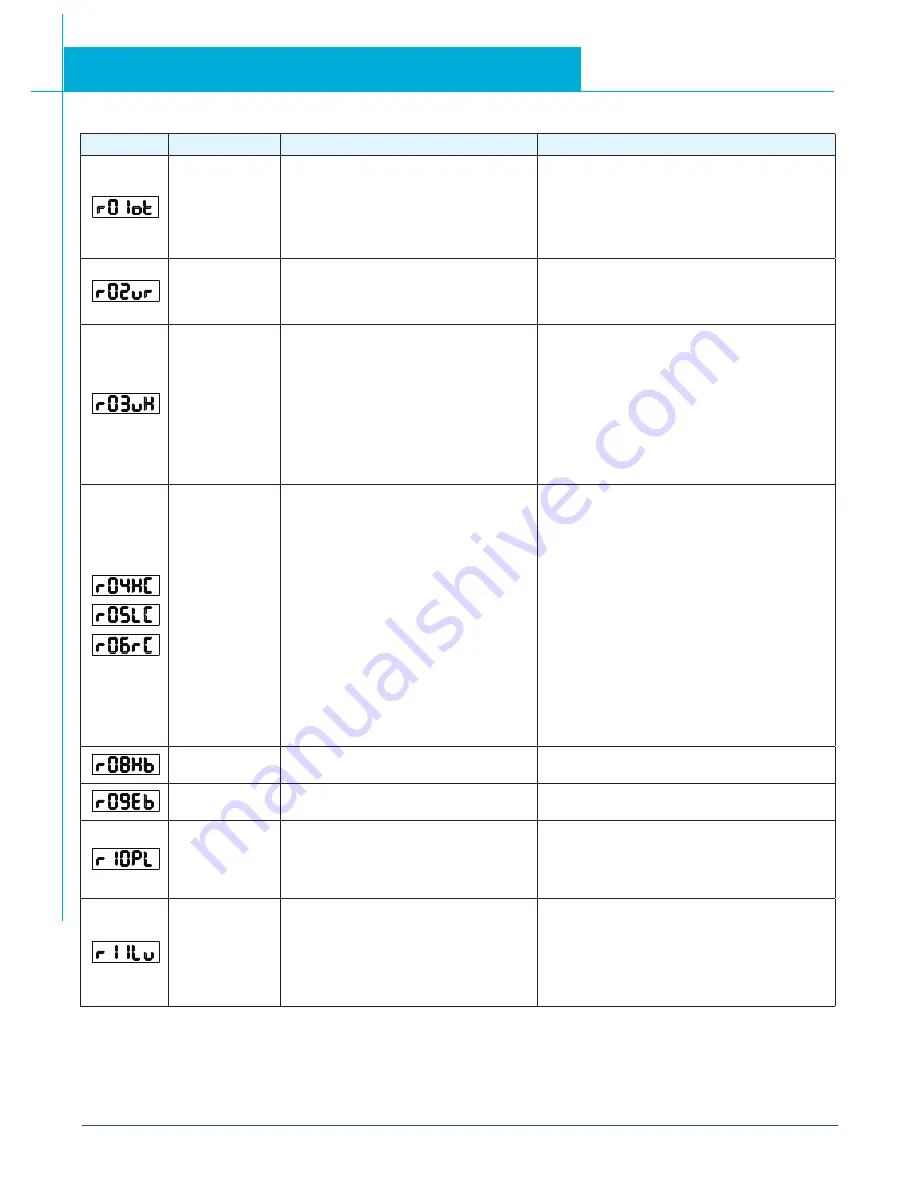
LED display
Description
Alarm type
Processing method
Drive over
temperature
Temperature of the heat sink or power
device has been risen over the specified
temperature.
1. Ambient temperature has risen over
the specified temperature.
2. Over-load
1. Improve the ambient temperature and
cooling condition.
2. Increase the capacity of the driver
and motor. Set up longer acceleration/deceleration
time. Lower the load
Internal voltage
fault
Drive internal voltage failure.
1. Please check supply power voltage
2. Please replace the drive with a new one, and
contact Applied Motion Products
Over voltage
Drive DC bus voltage is too high
220V series : 420V
1. Power supply voltage has exceeded the
permissible input voltage.
2. Disconnection of the regeneration discharge
resistor
3. External regeneration discharge
resistor is not appropriate and could not absorb
the regeneration energy.
4. Failure
Measure the voltage between lines of connector (L1,
L2 and L3).
1. Enter correct voltage.
2. Measure the resistance of the internal regeneration
resistor.
3. please measure the external resistor, Replace the
external resistor if the value is ∞.
4. Please contact Applied Motion Products or replace
the driver with a new one.
Over current
1. Failure of servo driver (failure of the
circuit, IGBT or other components)
2. Short of the motor wire (U, V and W)
3. Burnout of the motor
4. Poor contact of the motor wire.
5. Input pulse frequency is too high.
6. Motor is over load, command output torque
is larger than maximum torque, for a long
operating time.
7. Poor gain adjustment cause motor vibration,
and abnormal nosie.
8. Machine has collided or the load has gotten
heavy. Machine has been distorted.
9. Welding of contact of dynamic braking
relay due to frequent servo ON/OFF
operations.
1. Turn to Servo-ON, while disconnecting the motor. If
error occurs immediately, replace
with a new driver.
2. Check that the motor wire (U, V and W) is not
shorted, and check the branched out wire out of the
connector. Make a correct wiring connection.
3. Measure the insulation resistance between motor
wires, U, V and W and earth wire. In case of poor
insulation, replace the motor.
4. Check the balance of resister between each motor
line, and if unbalance is found, replace the motor.
5. Check the loose connectors. If they are, or pulled
out, fix them securely.
6. Adjust gain value settings.
7. Measuring brake voltage
8. Check drive and motor encoder and power wires.
9. please contact Applied Motion Products.
Bad hall sensor
Hall sensor fault
1. please check encoder connection
2. please check your drive motor configurations.
Encoder error
Encoder signal fault
please check encoder connection.
Position error
Position error value exceeds the position error
range set by parameter P-43 (PF).
1. Please check parameter P-43 (PF).
2. Please check drive gain value settings.
3. Please check the load factor of the regeneration
resistor, increase the capacity of the driver and the
motor, and loosen the deceleration time
Encoder error
1. Power supply voltage is low. Instantaneous
power failure has occurred
2. Lack of power capacity...Power supply
voltage has fallen down due to inrush
current at the main power-on.
3. Failure of servo driver (failure of the circuit)
Measure the voltage between lines of connector and
terminal block L1,L2,L3.
1. Increase the power capacity. Change the power
supply.
2. please check connections between L1,L2,L3. Please
refer to 4.1.5 drive power connection
3. please cpntact Applied Motion Products


