6 Operation | 6.5 Finding Appropriate Detector Settings
ZEISS
STEM Control
STEM imaging
mode
Output signal
Off
-
BF
S1
ADF
S2 + S3 + S4 + S5
ODF 0°
S2 - S3 + S4 - S5
ODF 90°
S3 - S2 - S4 + S5
HAADF
S6
ADF + HAADF
S2 + S3 + S4 + S5 +
S6
DF 0°
S2
DF 90°
S3
DF 180°
S4
DF 270°
S5
User defined name
Custom combination
of segments
Active segments
with +/- signs
Custom combination
of segments.
"+" on, "-" inverted
1. In the Crossbeam SEM Control panel, select the Imaging tab.
2. For displaying several channels of a aSTEM/STEM detector simultaneously, from the Menu
Bar, select Scanning > Quad Mode.
à
The Image Area is divided into 4 zones.
To select a detector for a zone, click in the zone.
An anchor symbol is displayed in the selected zone.
3. From the Signal A drop-down list, select a STEM detector, e.g. aSTEM1.
4. In the Panel Configuration Bar, double-click STEM Control.
To open the Panel Configuration Bar, from the Menu Bar, select Tools > Goto Panel.
à
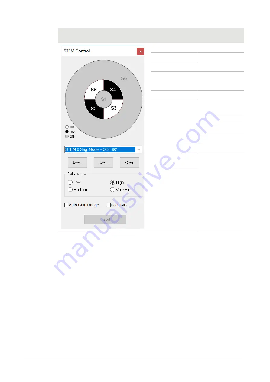
The STEM Control dialog is displayed.
In the upper section, the STEM Control dialog displays the status of the diode segments.
The status is either on (white), inverted (black), or off (gray).
5. Either select a STEM imaging mode from the STEM Seg. Mode/STEM 6 Seg. Mode drop-
down list or click a custom selection of diode segments to toggle its status between on, in-
verted, and off.
6. Set the Gain range.
Select between Low, Medium, High, or Very High.
7. For displaying several channels of a aSTEM/STEM detector simultaneously, repeat steps 3 to
6 for the other display zones.
90
Instruction Manual ZEISS Crossbeam 550L, Crossbeam 550 | en-US | Rev. 3 | 349500-8122-000
Summary of Contents for Crossbeam 550
Page 135: ......


