Getting Started
45
Installation location for the expansion bolts and punching requirement are shown
above.
2.
Lock the L-bracket with the M3× 8 screws.
3.
Move the setscrews on the L-bracket to the left holes.
4.
Lock the L-bracket to the wall with T4× 30 screws.
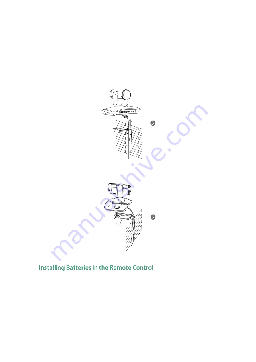
5.
Connect one end of the DVI cable to the VC110 all-in-one unit and put the other end
of the DVI cable through the L-bracket.
6.
Lock the VC110 all-in-one unit to the L-bracket, and then connect the other end of
the DVI cable to the cable hub.
Do the following:
1.
Open the battery cover on the back of the remote control.
2.
Insert the batteries with the correct polarity.
Summary of Contents for VC110
Page 1: ......
Page 4: ...iv ...
Page 8: ...Administrator s Guide for Yealink VC110 Video Conferencing Endpoint viii ...
Page 52: ...Administrator s Guide for Yealink VC110 Video Conferencing Endpoint 40 ...
Page 66: ...Administrator s Guide for Yealink VC110 Video Conferencing Endpoint 54 ...
Page 122: ...Administrator s Guide for Yealink VC110 Video Conferencing Endpoint 110 ...
Page 154: ...Administrator s Guide for Yealink VC110 Video Conferencing Endpoint 142 ...
Page 199: ...Configuring Endpoint Settings 187 3 Click Confirm to accept the change ...
Page 200: ...Administrator s Guide for Yealink VC110 Video Conferencing Endpoint 188 ...
Page 214: ...Administrator s Guide for Yealink VC110 Video Conferencing Endpoint 202 ...
Page 242: ...Administrator s Guide for Yealink VC110 Video Conferencing Endpoint 230 ...
Page 264: ...Administrator s Guide for Yealink VC110 Video Conferencing Endpoint 252 ...


