234
CHAPTER 7 - DIAGNOSTICS AND TROUBLESHOOTING
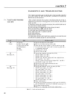
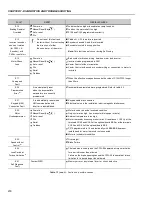
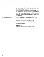
PROBLEM
POINT TO BE
CORRECTIVEACTION
CHECKED
Motor speed
Loose Connections
1. Disable the inverter, switch OFF the supply voltage and tighten all connections.
varies (oscillates)
2. Check if all internal connection is tightened.
Speed
1. Replace the speed potentiometer.
Potentiometer
Variation of the
1. Identify the cause of the variation.
external analog
reference
Parameters not set
1. Refer to chapter 6, parameters P410, P412, P161, P162, P175 and P176.
correctly (for P202 = 3 or 4)
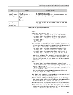
Motor speed too
Programming error
1. Check if the contents of P133 (Min. Speed) and P134 (Max. Speed) are according
high or too low
(reference limits)
to the motor and the application.
Signal of the
1. Check the control signal level of the reference.
reference control
2. Check the programming (gains and offset) in P234 to P247.
Motor Nameplate Data
1. Check if the used motor meets the application requirements.
Motor does not
1. Reduce P180 (set to 90 to 99 %).
reach rated speed or
it starts to oscillate
at rated speed for
P202 = 3 or 4 - Vector
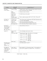
Display OFF
Connection of the
1. Check the Keypad connections to the inverter.
Keypad
Power Supply voltage
1. The power supply voltage must be within the following ranges:
220-230 V power supply: - Min: 187 V
- Max: 253 V
380-480 V power supply: - Min: 323 V
- Max: 528 V
500-600 V power supply: - Min: 425 V
- Max: 660 V
660-690 V power supply: - Min: 561 V
- Max: 759 V
Blown Fuse(s)
1. Replace the fuse(s).
Motor does not enter
1. Set P180, between 90 % and 99 %.
the field weakening
range
(for P202 = 3 or 4)
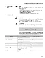
Motor speed too
Encoder signals or
Check the signals A - A, B - B according to figure 8.7. If this connections are
low and P009 = P169
power connections
correct invert two output phases, for instance U and V. Refer to figure 3.9.
or P170 (motor with
torque limitation),
for P202 = 4 -
Vector with encoder
Table 7.2 (cont.)
- Troubleshooting

