


48
CHAPTER 3 - INSTALLATION AND CONNECTION
CFW-09
L1
H1
A 1
B1
C1
D1
E mim.
Kit KMF
(*)
Size
mm
mm
mm
mm
mm
mm
mm
Through
(in)
(in)
(in)
(in)
(in)
(in)
(in)
Surface Mounting
item nº
Size 1
139
196
127
191
6
2.5
6
------------
(5.47)
(7.72)
(5.00)
(7.52)
(0.24)
(0.10)
(0.24)
Size 2
178
276
167
271
6
2.5
6
------------
(7.00)
(10.87)
(6.57)
(10.67) (0.24)
(0.10)
(0.24)
Size 3
225
372
150
400
37.5
14
8
417102514
(7.00)
(14.64)
(6.57)
(15.75) (1.44)
(0.59)
(0.31)
Size 4
252
452
150
480
51
14
8
417102515
(9.92)
(17.79)
(5.91)
(18.90) (1.97)
(0.59)
(0.31)
Size 5
337
527
200
555
68.5
14
10
417102516
(13.27)
(20.75)
(7.87)
(21.85) (2.70)
(0.59)
(0.35)
Size 6
13.27
652
200
680
68.5
14
10
417102517
(13.27)
(25.67)
(7.87)
(26.77) (2.70)
(0.59)
(0.39)
Size 7
337
812
200
840
68.5
14
10
417102518
(13.27)
(31.97)
(7.87)
(33.07) (2.70)
(0.59)
(0.39)
Size 8
412
952
275
980
68.5
14
10
417102519
(16.22)
(37.48)
(10.38) (38.58) (2.70)
(0.59)
(0.39)
Size 8E
412
1122
275
1150
68.5
14
10
(16.22)
(44.17)
(10.83) (45.27) (2.70)
(0.59)
(0.39)
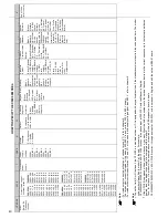
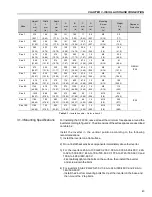
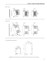
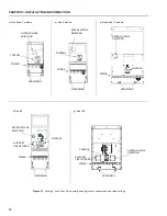
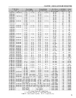
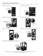
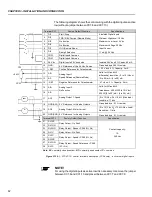
(*)
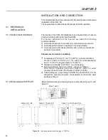
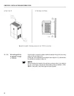
The Through Surface Mounting kit (kit-KMF) is a set of supports for the CFW-09 as shown on
figure 3.4 b).
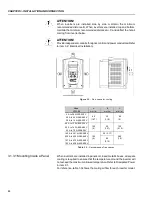
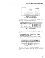
a) Sizes 1 and 2
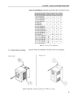
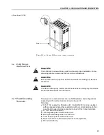
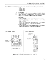
3.1.4 Keypad (HMI) and
Cover Removal
b) Sizes 3 to 8 and 8E
Screw
Figure 3.5 a) and b)
– Keypad (HMI) and cover removal procedure
Table 3.4
- Cutout dimensions and kits for CFW-09 through surface mounting


