


301
CHAPTER 8 - CFW-09 OPTIONS AND ACCESSORIES
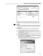
8.13.2 Interfaces Description
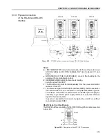
The physical connection between the inverters and the network master is
performed according to one of the standards below:
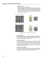
a. RS-232 (point-to-point, up to 10 m);
b. RS-485 (multipoint, galvanic isolation, up to 1000 m).
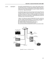
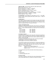
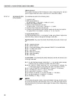
8.13.2.1 RS-485
This interface allows the connection of up to 30 inverters to a master (PC,
PLC, etc), attributing to each inverter an address (1 to 30) that must be set.
In addition to these 30 addresses, there are two other addresses to perform
special tasks:
Address 0:
any network inverter is inquired, independently of its address.
Only one inverter can be connected to the network (point-to-point) in
order to prevent short- circuits in the line interface.
Address 31:
a control can be transmitted to all inverters in the network
simultaneously, without acceptance recognition.
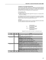
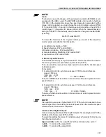
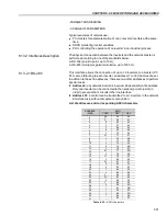
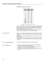
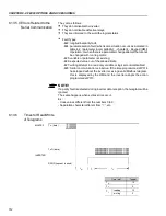
List of addresses and corresponding ASCII characters
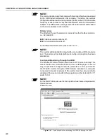
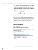
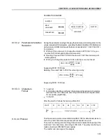
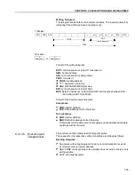
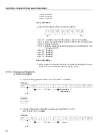
- PARAMETERS READING
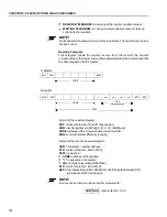
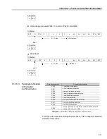
- CHANGE OF PARAMETERS
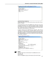
Typical examples of network use:
PC (master) for parameterization of one or several inverters at the same
time;
SDCD monitoring inverter variables;
PLC controlling the operation of an inverter in an industrial process.
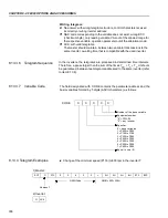
ADDRESS
(P308)
0
1
2
3
4
5
6
7
8
9
10
11
12
13
14
15
16
17
18
19
20
21
22
23
24
25
26
27
28
29
30
31
ASCII
CHAR
DEC
HEX
@
64
40
A
65
41
B
66
42
C
67
43
D
68
44
E
69
45
F
70
46
G
71
47
H
72
48
I
73
49
J
74
4A
K
75
4B
L
76
4C
M
77
4D
N
78
4E
O
79
4F
P
80
50
Q
81
51
R
82
52
S
83
53
T
84
54
U
85
55
V
86
56
W
87
54
X
88
58
Y
89
59
Z
90
5A
]
91
5B
\
92
5C
[
93
5D
^
94
5E
_
95
5F
Table 8.20 -
ASCII characters


