258
CHAPTER 8 - CFW-09 OPTIONS AND ACCESSORIES
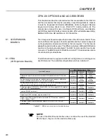
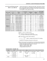
Cable Length
1 m (3 ft)
2 m (6 ft )
3 m (10 ft)
5 m (15 ft)
7.5 m *(22 ft)
10 m * (30 ft )
WEG Part N
o
0307.6890
0307.6881
0307.6873
0307.6865
0307.6857
0307.6849
*
These cables require the use of the remote
HMI-09 frame
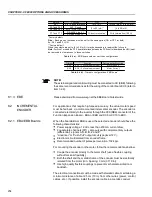
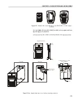
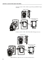
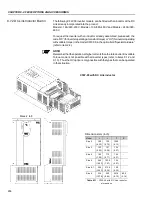
The CFW-09 keypad (both the standard or the LED display only) can be installed
directly on the inverter cover or remotely. If the keypad is installed remotely,
the HMI-09 Frame can be used. The use of this frame improves the visual
aspect of the remote keypad, as well as provides a local power supply to
eliminate voltage drop problems with long cables. It is necessary to use the
frame
when the keypad cable is longer than 5 m (15 ft).
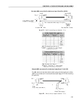
The table below shows the standard cable lengths and their part numbers:
Table 8.6
- CFW-09 keypad cables
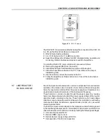
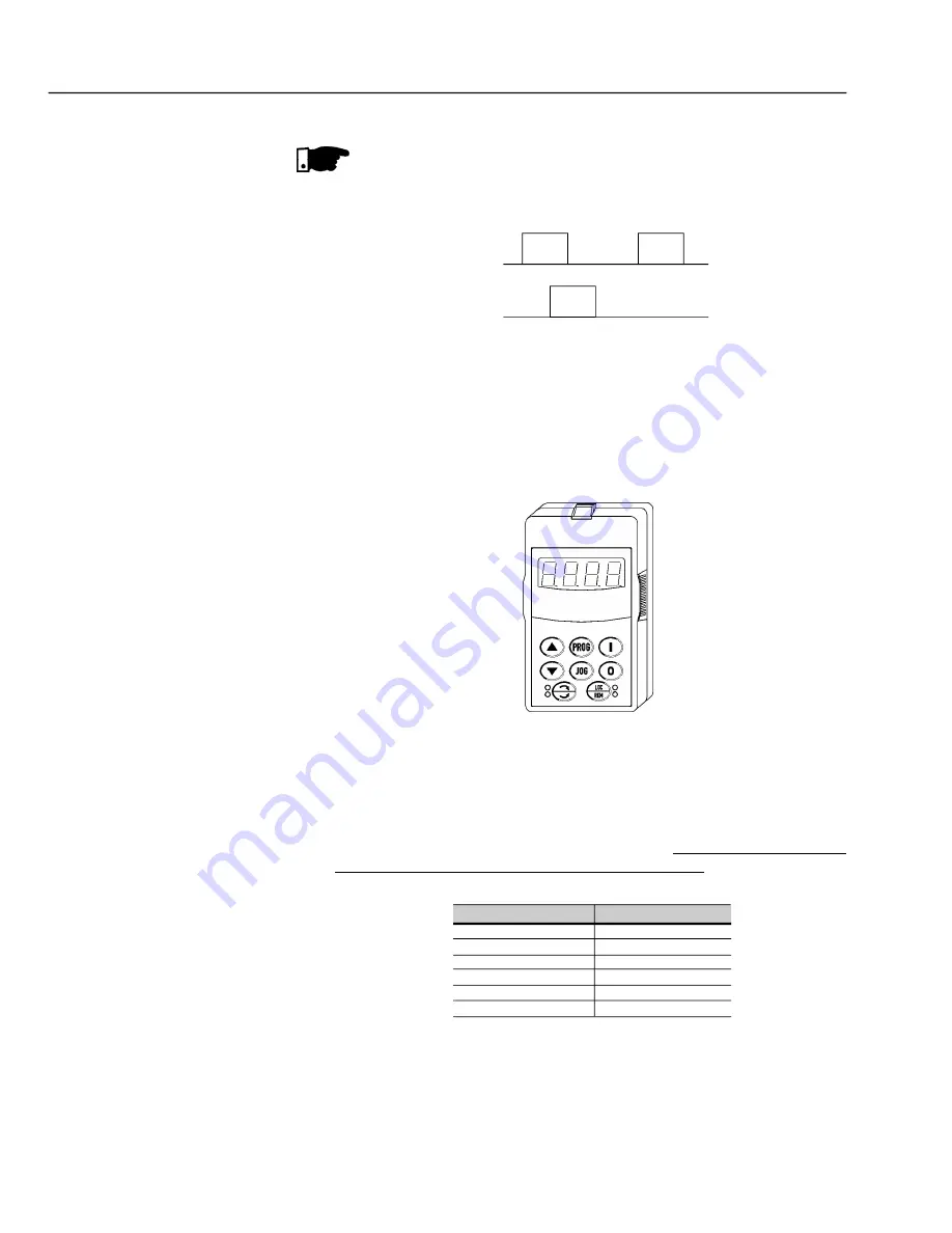
Figure 8.12
- Keypad with LED display only
8.4
REMOTE KEYPAD
AND CABLES
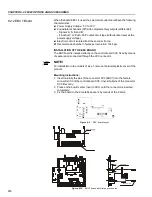
The keypad cable must be installed separately from the power cables, following
the same recommendations as for the CC9 control board (refer to item 3.2.6).
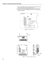
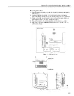
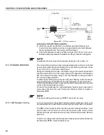
For assembling refer to details in figure 8.13 and 8.14.
The CFW-09 standard Keypad (HMI) is provided with LEDs and LCD display.
It can also be supplied with an LED Display only.
In this case the keypad model number is: HMI-CFW-09-LED. It operates in
the same way as the standard keypad, but it does not show the text messages
of the LCD and does not provide the copy function.
The dimensions and the electrical connections are the same as for the standard
keypad. Refer to item 8.4.
8.3
KEYPAD WITH
LEDs ONLY
NOTE!
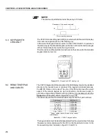
The maximum permitted encoder frequency is 100 kHz.
Sequence of the encoder signals:
Motor running clockwise
B
t
A
t

