202
CHAPTER 6 - DETAILED PARAMETER DESCRIPTION
NOTE!
Cares with Application:
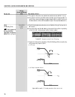
The use of the line reactance or DC choke is mandatory to limit
the inrush current when the network is reestablished.
NOTE!
The function Ride-Through in Vector Mode for models 107 Ato 472 A/
500-690 V and 100 A to 428 A/660-690 V works only up to a
maximum time of 2 s. In these models the control power supply is
not fed from the DC Link, it is a separate power supply with 2 s
autonomy.
NOTE!
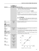
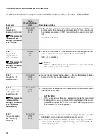
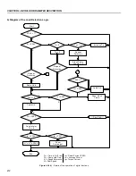
To activate the Ride-Through, the line supply must fall to a value
lower than (P321
1.35).
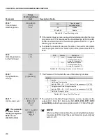
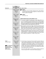
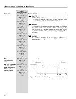
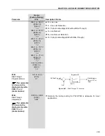
Range
[Factory Setting]
Parameter
Unit
Description / Notes
324 V to 513 V
(P296 = 2)
[446 V]
1 V
356 V to 564 V
(P296 = 3)
[490 V]
1 V
388 V to 615 V
(P296 = 4)
[535 V]
1 V
425 V to 674 V
(P296 = 5)
[588 V]
1 V
466 V to 737 V
(P296 = 6)
[644 V]
1 V
486 V to 770 V
(P296 = 7)
[672 V]
1 V
559 V to 885 V
(P296 = 8)
[773 V]
1 V
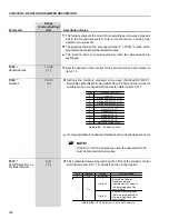
P323
(6)
178 V to 282 V
Ud Loss Recover
(P296 = 0)
Level
[267 V]
1 V
307 V to 487 V
(P296 = 1)
[461 V]
1 V
324 V to 513 V
(P296 = 2)
[486 V]
1 V
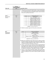
This parameter
is shown on the
display(s) only when
P202 = 3 or 4
(Vector Control)
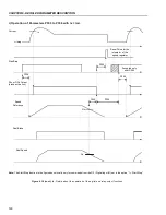
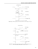
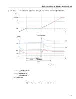
Figure 6.42
- Actuation of the Ride-Through function in Vector Control mode
Nominal
Loss Recover (P323)
Line Loss (P321)
Ride-Through (P322)
Undervoltage (75 %)
E02
t0 t1
t2
t3 t4 t5
t
(t)
Ud

