


315
CHAPTER 8 - CFW-09 OPTIONS AND ACCESSORIES
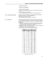
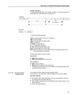
Address:
The master initiates the communication by sending one byte with the address
of the slave to which the message is addressed. The slave with the right slave
address initiates the message with its own address. The master can also
send a message destined to address 0 (zero), which means that the message
is destined to all network slaves (broadcast). In this case no slave will answer
to the master.
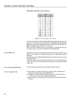
Function Code:
This field contains an only byte, where the master specifies the type of service
or the function requested to the slave (read, write, etc.). According to the
protocol, each function is used to access a specific data type. In the CFW-09
all data are available as holding type registers (referenced from the address
40000 or’ 4x’). Besides these registers, the inverter status (enabled/disabled,
with error/no error and the command for the inverter (Start/Stop, Run CW/
CCW, etc.) can be also accessed through the coils read/write functions or the
internal bits (referenced from the address 00000 or ‘0x’ on).
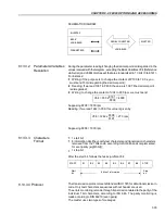
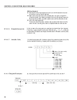
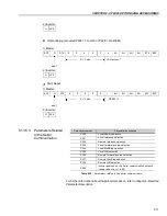
Data Field:
This field has variable length. The format and the content of this field depend
on the used function and transmitted values. This field and the respective
functions are described in item 8.14.3.
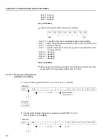
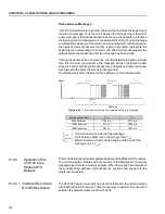
CRC:
The last part of the message is the field for checking the transmission errors.
The used method is the CRC-16 (Cycling Redundancy Check). This field is
formed by two bytes, where the least significant byte (CRC-) is transmitted
first and only then the most significant byte is transmitted (CRC+).
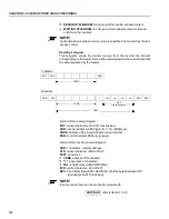
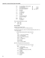
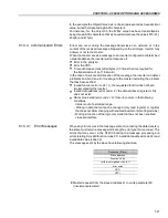
CRC calculation is started by loading a 16-bit variable (mentioned from now
on as CRC variable) with FFFFh value. Then following steps are executed with
the following routine:
1. The first message byte (only the data bits - the start bit, parity bit and stop
bit are not used) is submitted to the XOR logic (OR exclusive) with the 8
least significant bits of the CRC variable, returning the result to the CRC
variable.
2. Then the CRC variable is displaced one position to the right, in the direction
of the least significant bit and the position of the most significant bit is
filled out with zero 0 (zero).
3. After this displacement, the flag bit (bit that has been displaced out the
CRC variable) is analyzed, by considering the following:
If the bit value is 0 (zero), no change is made.
If the bit value is 1, the CRC variable content is submitted to XOR
logic with a constant A001h value and the value is returned to the
CRC variable.
4. Repeat steps 2 and 3 until the eight displacements have been realized.
5. Repeat the steps 1 to 4, by using the next byte message until the whole
message have been processed. The end content of the CRC variable is
the value of the CRC field that is transmitted at the end of the message.
The least significant part is transmitted first (CRC), only then the most
significant part (CRC+) is transmitted.


