


136
CHAPTER 6 - DETAILED PARAMETER DESCRIPTION
Range
[Factory Setting]
Parameter
Unit
Description / Notes
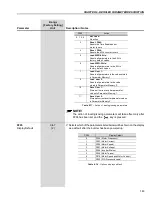
P151
(6)
DC Link Voltage
339 to 400 (P296 = 0)
Regulation Level
[ 400 ]
For Vector Control
1 V
(P202 = 3 or 4)
585 to 800 (P296 = 1)
[ 800 ]
1 V
616 to 800 (P296 = 2)
[ 800 ]
1 V
678 to 800 (P296 = 3)
[ 800 ]
1 V
739 to 800 (P296 = 4)
[ 800 ]
1 V
809 to 1000 (P296 = 5)
[ 1000 ]
1 V
885 to 1000 (P296 = 6)
[ 1000 ]
1 V
924 to 1000 (P296 = 7)
[ 1000 ]
1 V
1063 to 1200 (P296 = 8)
[ 1200 ]
1 V
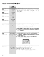
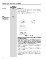
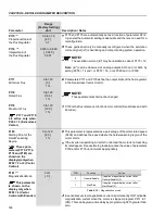
P151 defines the level for the DC Link voltage regulation during braking.
The time of the deceleration ramp is automatically extended, thus avoiding
overvoltage error (E01).
The DC Link voltage regulation has two modes of operation:
1. With losses (Optimal braking) – set P150 to 0. In this mode the flux
current is modulated so as to increase the losses in the motor, there
by increasing the braking torque. It works better with lower efficiency
motors (smaller motors). It is not recommended for motors bigger
than 75 hp/55 kW. Refer to explanation below.
2. Without losses – set P150 to 1. Only the DC Link voltage regulation
is active.
NOTE!
P151 factory setting is set at maximum this disables the DC Link
voltage regulation. To enable it, adjust according to table 6.8.
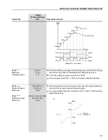
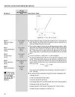
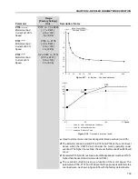
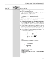
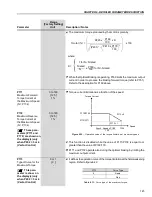
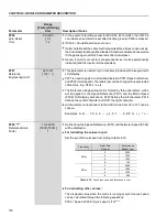
Optimal Braking:
The Optimal Braking is a unique method of stopping the motor that
provides more braking torque than DC Injection Braking without requiring
Dynamic Braking components. In the case of DC Braking, except for the
friction losses, only the rotor losses are used to dissipate the stored
energy due to the driven mechanical load.
With Optimal Braking, both the total motor losses and the inverter losses
are used. In this way, it is possible to achieve a braking torque of
approximately 5 times higher than with the DC braking (Refer to figure
6.15).
This feature allows high dynamic performance without the use of a
Dynamic Braking resistor.
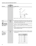
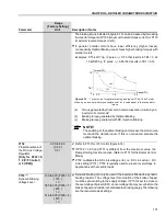
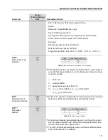
Figure 6.15 shows a Torque x Speed curve of a typical 7.5 kW/10 hp, IV
pole motor. The braking torque developed at full speed, with torque (P169
and P170) limited by the CFW-09 at a value equal to the motor rated
torque, is given by TB1 point (figure 6.15).
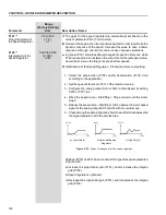
TB1 value depends on the motor efficiency and disregarding the friction
losses it is given by the following equation:
Where:
= motor efficiency
For the case in figure 6.15, the motor efficiency at full load condition is
84 %
= 0.84, that results in TB1 = 0.19 or 19 % of the motor rated
torque. Starting at TB1 point, the braking torque varies in the reverse
proportion of the speed (1/N). At low speeds, the braking torque reaches
the torque limit level set by the inverter. For the case of figure 6.15, the
torque limit (100 %) is reached when the speed is 20 % of the rated
speed.
TB1 =
1 -


