171
CHAPTER 6 - DETAILED PARAMETER DESCRIPTION
Range
[Factory Setting]
Parameter
Unit
Description / Notes
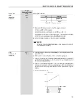
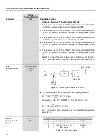
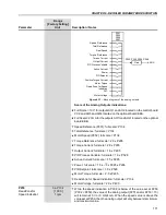
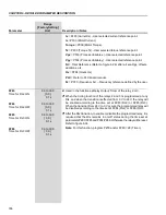
Scale of the Analog Outputs indications:
Full Scale = 10 V: for outputs AO1 and AO2 located on the control board
CC9 and AO3 and AO4 located on the optional board EBA.
Full Scale = 20 mA for the outputs AO1I and AO2I located on the optional
board EBB.
Speed Reference (P001): full scale = P134
Total Reference: full scale = P134
Motor Speed (P002): full scale = P134
Torque Reference: full scale = 2.0 x P295
Torque Current: full scale = 2.0 x P295
Output Current: full scale = 1.5 x P295
PID Process Variable: full scale = 1.0 x P528
Active Current: full scale = 1.5 x P295
Power: full scale = 1.5 x 3 x P295 x P296
PID Setpoint: full scale = 1.0 x P528
Motor Torque: full scale = 2.0 x P295
Dead Zone for Speed Indication: full scale = P134
Motor Voltage: full scale = 2.0 x P400
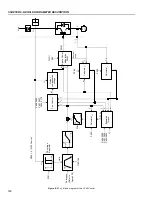
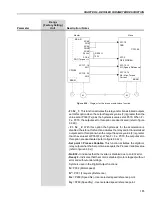
Figure 6.31
- Block diagram of the analog outputs
P251
P253
P255
P257
Gain
AOX
P252, P254, P256, P258
Power
Active Current
Output Current
Torque Current
Torque Reference
Real Speed
Total Reference
Speed Reference
PID Process Variable
PID Setpoint
Positive Torque Current
Motor Torque
PLC
Dead Zone for Speed
Indication
P259
0 a P134
Dead Zone for
[ 1000 ]
Speed Indication
1 rpm
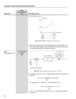
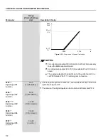
While the speed indication in P002 is below of the value set at P259
(P002 < P259), the value of the analog output (P251 and/or P253 = 13)
will remain at 0 V or 0 mA/4 mA. When the speed value is above the
value set at P259, then the analog output will vary between its minimum
and maximum value.
Motor Voltage


