172
CHAPTER 6 - DETAILED PARAMETER DESCRIPTION
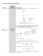
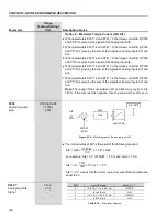
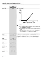
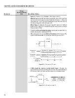
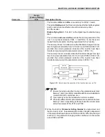
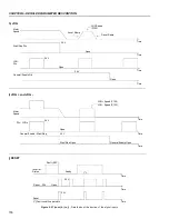
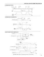
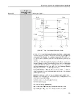
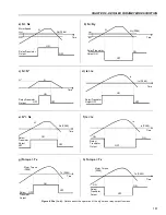
Figure 6.32
- Dead zone for speed indication
NOTES!
For current analog output (0 to 20 mA or 4 to 20 mA) it is necessary
to use the EBB expansion board.
A voltage analog output (0 to 10 V) is available at the CC9 control
board.
The analog outputs AO3 and AO4 do not have this function, i.e.,
set P255 and/or P257 = 13 will program no function.
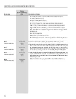
Range
[Factory Setting]
Parameter
Unit
Description / Notes
P263
(1)
0 to 3
Digital Input DI1
[ 1 (Start/Stop) ]
Function
-
P264
(1)
0 to 8
Digital Input DI2
[ 0 (FWD/REV) ]
Function
-
P265
(1) (8)
0 to 22
Digital Input DI3
[ 0 (Not Used) ]
Function
-
P266
(1)
0 to 22
Digital Input DI4
[ 0 (Not Used) ]
Function
-
P267
(1)
0 to 22
Digital Input DI5
[ 3 (JOG) ]
Function
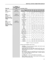
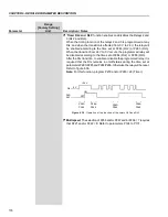
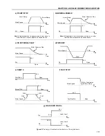
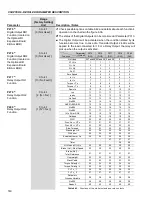
Check possible options on table 6.41 and details about each function’s
operation on figure 6.37.
The status of the digital inputs can be monitored at Parameter P012.
A01
A02
20 mA
10 V
4 mA
0 V
P259
P134
n


