109
CHAPTER 5 - START-UP
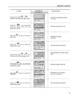
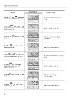
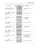
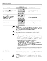
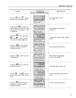
NOTES!
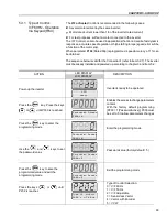
(1)
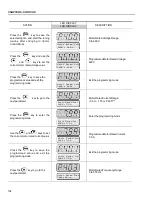
P401 maximum value is 1.8 x P295 for model 4.2 A/500-600 V and 1.6 x P295
for models 7 A and 54 A/220-230 V; 2.9 A and 7 A/500-600 V; 107 A,
147 A and 247 A/500-690 V; 100 A, 127 A and 340 A/660-690 V.
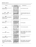
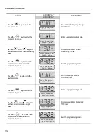
(2)
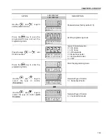
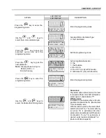
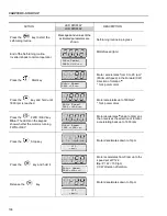
The self-tuning routine can be cancelled by pressing the
key.
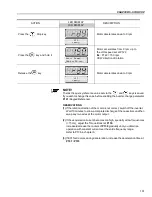
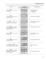
(3)
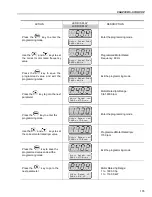
The last speed reference value set via the
and
keys is saved.
If you wish to change this value before enabling the inverter, change parameter
P121
(Keypad Reference).
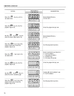
(4)
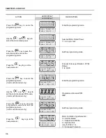
If E01 fault occurs during deceleration, you must increase deceleration time
at
P101 / P103
.
OBSERVATION:
If the rotation direction of the motor is not correct, switch off the inverter. Wait 10
minutes to allow a complete discharge of the capacitors and swap any two wires
at the motor output. If motor is equipped with an encoder, change the phase of
the encoder connections (exchange channel A and A).
ATTENTION!
In Vector Mode (P202 = 3 or 4), when the command STOP (START/STOP) is
enabled - refer to figure 6.37, the motor will decelerate up to zero speed, but it
maintains the magnetization current (no-load current). This maintains the motor
with rated flux and when the next START command is given, it will achieve a
quick response.
For self-ventilated motors with no-load current higher than 1/3 of the rated current
(generally small motors lower than 10 hp), it is recommended that the motor
does not stay in this condition (magnetization current) for a long time, since it
may overheat. In these cases, we recommend to deactivate the command “Ge-
neral Enable” (when the motor has stopped), thus decreasing the motor current
to zero when stopped.
Another way to disable magnetization current with the motor stopped is to program
P211 to 1 (zero speed disable is ON) for both vector modes and, for vector with
encoder, still another option is to program P181 to 1 (Magnetization mode). If
magnetization current is disabled with the motor stopped, there will be a delay at
start while the flux builds up.
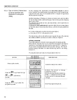
The VVW (Voltage Vector WEG) Control Mode follows the same philosophy of
the V/F Control. The VVW Control allows a reasonable improvement of the steady-
state inverter performance: it results in a better speed regulation and in a higher
torque capability at low speeds (frequencies lower than 5 Hz).
As a result, the frequency (speed) range of the system is increased with respect
to the V/F Control. Other advantages of this control are the simplicity and ease of
setting.
The VVW Control uses the stator current measurement, the stator resistance
(that can be obtained from the self-tuning routine) and the motor nameplate data
to automatically estimate the torque value, the output compensation voltage value
and, consequently, the slip compensation value, which substitute the function of
parameters P137 and P138.
5.3.3 Type of Control:
VVW - Keypad
Operation

