220
CHAPTER 6 - DETAILED PARAMETER DESCRIPTION
6.5
SPECIAL FUNCTIONS
PARAMETERS -
P500 to P699
6.5.1 PID Regulator
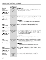
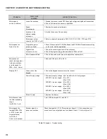
The function of the PID regulator is activated by setting P203 to 1.
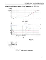
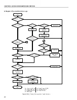
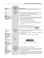
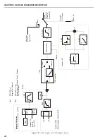
Figure 6.47 shows the block diagram of the Academic PID regulator.
The transference function in the frequency domain of the Academic PID
regulator is:
6.5.2 Description
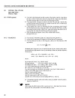
Substituting the integrator by a sum and the derivative by the incremental quotient,
we will obtain an approximate value for the discrete (recursive) transfer equation
shown below:
where:
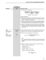
Kp (Proportional Gain): Kp = P520 x 4096;
Ki (Integral Gain)
: Ki = P521 x 4096 = [Ta/Ti x 4096];
Kd (Differential Gain) : Kd = P522 x 4096 = [Td/Ta x 4096];
Ta = 0.02 s (sampling period of the PID Regulator);
SP*: reference, has 13 bits max. (0 to 8191);
X: process variable (or controlled), read at AI2 or AI3, has 13 bits maximum;
y(kTa): current PID output, has 13 bits maximum;
y(k-1)Ta: previous OPID output;
e(kTa): current error [SP*(k) – X(k)];
e(k-1)Ta: previous error [SP*(k-1) – X(k-1)];
e(k-2)Ta: error of the two previous samplings [SP*(k-2) – X(k-2)].
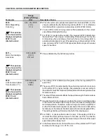
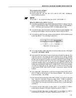
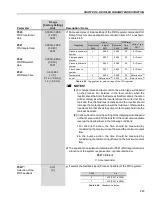
The feedback signal must be sent to the analog inputs AI2' and AI3' (refer to
figure 6.29 and 6.30).
NOTE!
When using the PID function P233 must be set to 1, otherwise the minimum
speed (P133) will be added to the PID feedback via AI2.
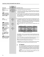
The CFW-09 is fitted with the PID regulator that can be used for closed loop
process control. This function acts as a proportional, integral and derivative
regulator, superimposed on the normal inverter speed control.
The speed will be changed in order to maintain the process variable (the
variable that should be controlled - for instance: water level of a container) at
the desired value, set in the setpoint.
This regulator can control, for example, the flow in a piping system through
the flow feedback to the analog input AI2 or AI3 (selected via P524), and the
flow reference set at P221 or P222 - AI1, when the inverter drives the motor of
a pump that circulates the fluid through this piping system.
Other application examples: level control, temperature control,
dosing control, etc.
]
sTd
sTi
1
1
)[
s
(
e
Kp
)
s
(
y
)]
Ta
)
2
k
(
e
Ta
)
1
k
(
e
2
)
kTa
(
e
(
Kd
Ta
)
1
k
(
Kie
)
Ta
)
1
k
(
e
)
kTa
(
e
[(
Kp
Ta
)
1
k
(
y
)
kTa
(
y

