


227
CHAPTER 6 - DETAILED PARAMETER DESCRIPTION
Range
[Factory Setting]
Parameter
Unit
Description / Notes
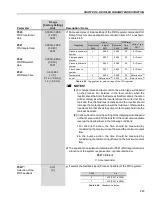
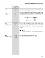
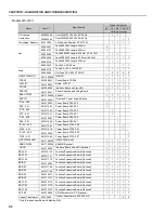
P535
0 to 100
Wake Up Band
[ 0 ]
1 %
P536
(1)
0 or 1
Automatic Set of
[ 0 ]
P525
-
The value of this parameter is used along with P212 (Condition to Leave
Zero Speed Disable), providing additional condition to leave zero speed
disable, that is, error of PID > P535. Refer to P211 to P213.
When the setpoint of the PID regulator is by HMI (P221/P222 = 0) and
P536 is zero (active) by commutating from manual to automatic, the
process variable value will be loaded at P525. In this way you prevent
PID oscillations during the commutation from “Manual” to “Automatic”.
P536
Action Type
0
Active
1
Inactive
Table 6.69 -
Automatic set of P525
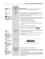
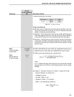
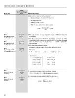
P537
0 to 100
Hysteresis for the
[ 1 ]
Set Point =
1 %
Process Variable
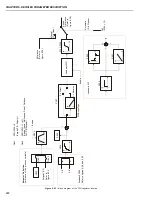
When the Set Point value is equal to the Process Variable and it is
within the range defined by the hysteresis value (set at parameter P537),
the digital or relay output set to the option Set Point = Process Variable
(SP = PV) is activated and remains in this condition until the process
variable reaches a value outside of the hysteresis range (refer to figure
6.39 v)).
NOTE!
This function is enabled only in the automatic mode and when
P203 = 1.
P538
0.0 to 50.0
Hysteresis VPx/VPy
[ 1.0 ]
0.1 %
It is used in functions of the digital and relay outputs:
Process Variable > VPx and Process Variable < VPy


