

176
CHAPTER 6 - DETAILED PARAMETER DESCRIPTION
Range
[Factory Setting]
Parameter
Unit
Description / Notes
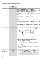
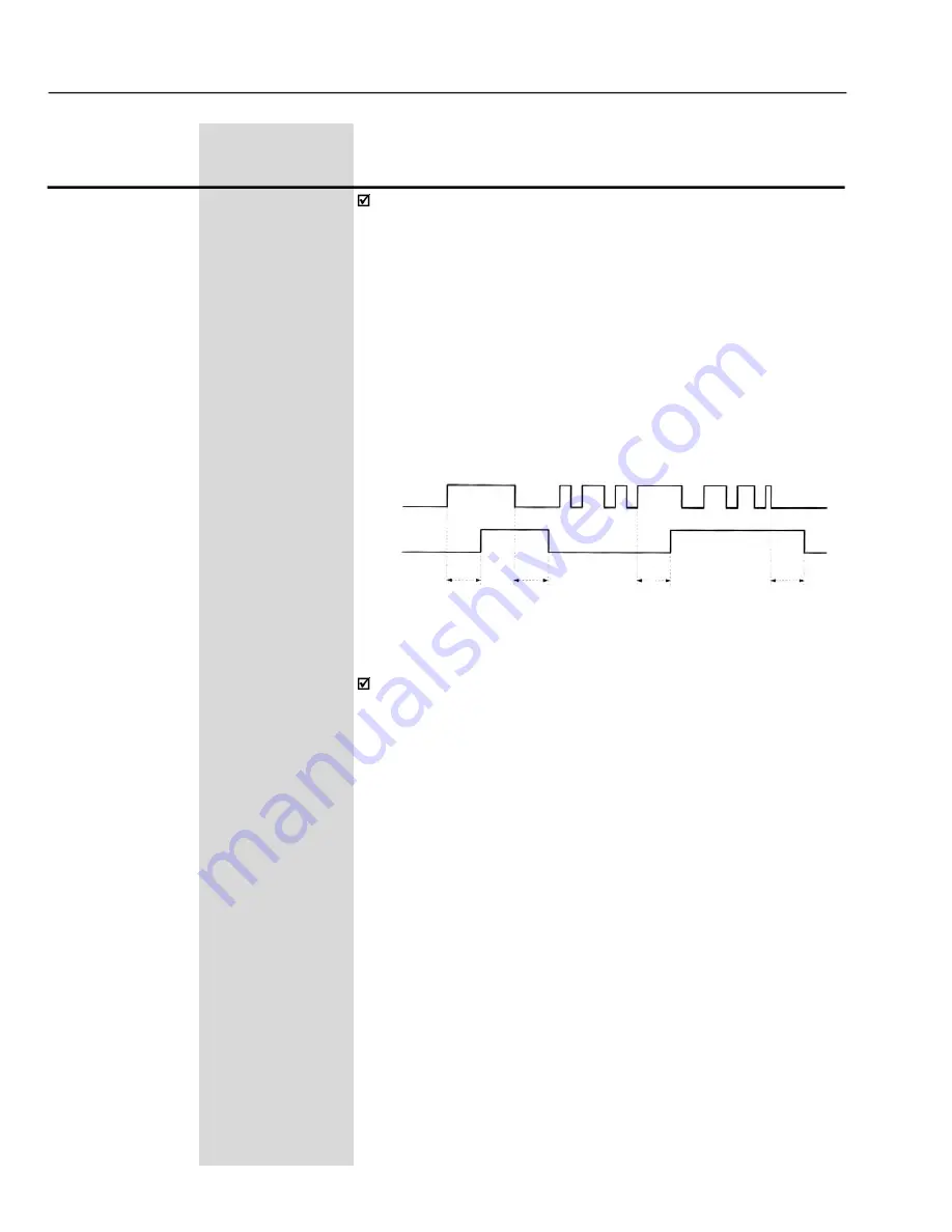
+24 V
0 V
DIx
RL2/
RL3
ON
OFF
P283/
P285
P284/
P286
P283/
P285
P284/
P286
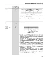
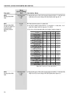
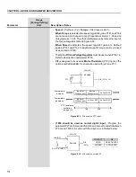
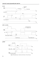
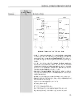
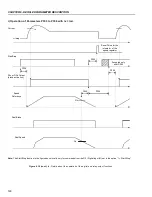
Figure 6.36
- Operation of the function of the timers RL2 and RL3
Multispeed:
The selection of P266 and/or P267 and/or P268 = 7 requires
that P221 and/or P222 = 8. Refer to parameters P124 to P131.
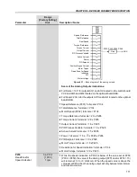
‘Timer RL2 and RL3’
function enables and disables the Relays 2 and
3 (RL2 and RL3).
When the timing function of the relays 2 and 3 is programmed at any
DIx, and when the transition is effected from 0 V to 24 V, the relay will
be enabled according to the time set at P283 (RL2) or P285 (RL3).
When the transition from 24 V to 0 V occurs, the programmed relay will
be disabled according to the time set at P284 (RL2) or P286 (RL3).
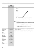
After the DIx transition, to enable or disable the programmed relay, it is
required that the DIx remains in on/off status during the time set at
parameters P283/P285 and P284/P286. Otherwise the relay will be reset.
Refer to figure 6.36.
Note:
For this function, program P279 and/or P280 = 28 (Timer).


