210
CHAPTER 6 - DETAILED PARAMETER DESCRIPTION
Range
[Factory Setting]
Parameter
Unit
Description / Notes
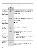
Time that the CFW-09 waits before starting the load detection after the
stabilization speed has been reached.
P363
(1)
0.1 to 10.0
Stabilization Time
[ 0.1 ]
0.1 s
Available only
if P361 = 1 (On)
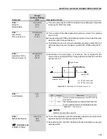
Time that the CFW-09 waits to commutate the digital (DOx) and relay
outputs set to the option “Slack Cable Detection”. If the Slack Cable
condition is no longer valid, the CFW-09 resets the digital or relay outputs.
NOTE!
When P364 = 0, the detection logic of slack cable is disabled.
P364
(1)
0.0 to 60.0
Slack Cable Time
[0.0]
0.1 s
Available only
if P361 = 1 (On)
Output current value used to detect the slack cable condition.
P365
(1)
0.0 to 1.3 x P295
Slack Cable Level
[0.1 x P295]
0.1 A
Available only
if P361 = 1 (On)
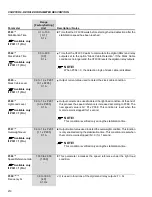
Output current value used to detect the light load condition. At the end of
this process the speed reference is increased according to P368. The
new speed value is N = N* x P368. This condition is reset when the
motor remains stopped for 1 second.
NOTE!
This condition is verified only during the stabilization time.
P366
(1)
0.0 to 1.3 x P295
Light Load Level
[0.3 x P295]
0.1 A
Available only
if P361 = 1 (On)
Output current value used to detect the overweight condition. This function
is only enabled during the stabilization time. This condition is reset when
the motor remains stopped (N = 0) for 1 second.
NOTE!
This condition is verified only during the stabilization time.
P367
(1)
0.0 to 1.8 x P295
Overweight Level
[1.1 x P295]
0.1 A
Available only
if P361 = 1 (On)
This parameter increases the speed reference under the light load
condition.
P368
(1)
1.000 to 2.000
Speed Reference Gain
[1.000]
-
Available only
if P361 = 1 (On)
It is used in functions of the digital and relay outputs: F > Fx.
P369
(2) (11)
0.0 to 300.0
Frequency Fx
[4.0]
0.1 Hz

