44
CHAPTER 3 - INSTALLATION AND CONNECTION
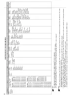
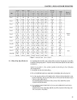
Table 3.2
- Recommended free spaces
A
B
C
mm (in)
mm (in)
mm (in)
40
30
50
(1.57)
(1.18)
(2)
100
40
130
(4)
(1.57)
(5.12)
55 (2.17)
150
250
(6)
80
(10)
(3.15)
Model
CFW-09
6 A to 28 A/220-230 V
3.6 A to 24 A/380-480 V
2.9 A to 14 A/500-600 V
45 A to 130 A/220-230 V
30 A to 142 A/380-480 V
22 A to 79 A/500-600 V
180 A to 361 A/380-480 V
450 A to 600 A/380-480 V
107 A to 472 A/500-690 V
100 A to 428 A/660-690 V
When inverters are installed in panels or closed metallic boxes, adequate
cooling is required to ensure that the temperature around the inverter will
not exceed the maximum allowed temperature. Refer to Dissipated Power
in item 9.1.
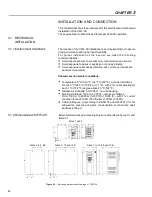
For reference, table 3.3 shows the cooling airflow for each inverter model.
3.1.3.1 Mounting Inside a Panel
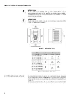
ATTENTION!
When inverters are installed side by side, maintain the minimum
recommended distance B. When inverters are installed top and bottom,
maintain the minimum recommended distance A + C and deflect the hot air
coming from inverter below.
ATTENTION!
Provide independent conduits for signal, control and power conductors (Refer
to item 3.2: Electrical Installation).
A
B
C
B
5
0
m
m
2
in
Figure 3.2
- Free space for cooling

