150
CHAPTER 6 - DETAILED PARAMETER DESCRIPTION
Range
[Factory Setting]
Parameter
Unit
Description / Notes
P206
0 to 255
Auto-Reset
[ 0 ]
Time
1 s
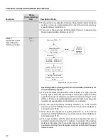
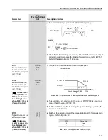
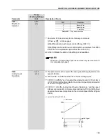
In the event of a fault trip, except for E09, E24, E31 and E41, the CFW-09
can initiate an automatic reset after the time given by P206 is elapsed.
If P206
2 Auto-Reset does not occur.
If after Auto-Reset the same fault is repeated three times consecutively,
the Auto-Reset function will be disabled. A fault is considered consecutive
if it happens again within 30 seconds after Auto-Reset.
Hence, if an error occurs four consecutive times, it will be permanently
indicated (and the inverter will be disabled).
P207
32 to 127
Reference
[ 114 = r ]
Engineering Unit 1
-
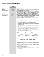
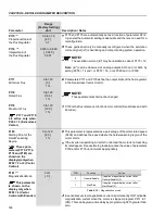
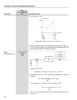
This parameter is useful only for inverters provided with a keypad with
LCD display.
P207 is used to apply a customized display to P001 (Speed reference)
and P002 (motor speed). The letters rpm can be changed to user selected
characters, E.g. CFM, L/s, etc.
The Reference Engineering Unit is formed by three characters, which
will be applied to the Speed Reference (P001) and the Motor Speed
(P002) LCD display indications. P207 defines the left character. P216
defines the center character and P217 the right character.
All characters correspondent to the ASCII code from 32 to 127 can be
chosen.
Examples: A, B, ... , Y, Z, a, b, ... , y, z, 0, 1, ... , 9, #, $, %, (, ), *, +,...
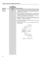
Frequency
Motor Pole
Syncronous
Number
Speed - rpm
50 Hz
2
3000
4
1500
6
1000
8
750
60 Hz
2
3600
4
1800
6
1200
8
900
P208
(2)(11)
1 to 18000
Reference Scale
[ 1800 (1500) ]
Factor
1
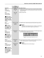
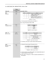
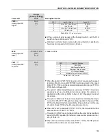
Defines how the Speed Reference (P001) and the Motor Speed (P002)
will be displayed.
For indicating the values in rpm:
Set the synchronous speed according to table 6.19.
For indicating other values:
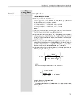
The displayed value when the motor is running at synchronous speed
can be calculated through the following equations:
P002 = Speed x P208 / Sync speed x (10)
P210
Table 6.19
- Synchronous speed reference in rpm

