background image

135

CHAPTER 6 - DETAILED PARAMETER DESCRIPTION

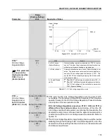
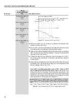
E01 - Overvoltage Level

Regulation Level

P151

Nominal

DC Link Voltage (Ud) (P004)

Range

[Factory Setting]

Parameter

Unit

Description / Notes

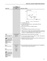
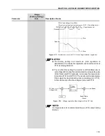
Time

Time

Speed

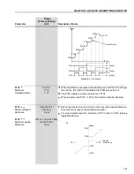
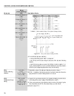
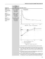
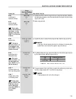
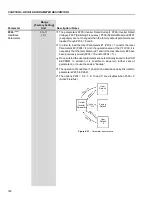
Figure 6.13

- Deceleration curve with DC Link voltage limitation (regulation)

NOTES!

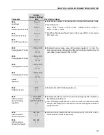
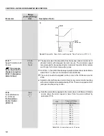
The factory setting is at maximum (Link regulation is
deactivated). To activate this regulation, we recommend to set
P151 according table 6.8.

If even after this setting the inverter is still disabled due to
overvoltage (E01) during the load acceleration, increase the value
of the Parameter P152 gradually, or increase the deceleration
ramp time (P101 and/or P103). The inverter will not decelerate,
if the supply line is permanently under overvoltage Ud > P151).
In this case reduce the line voltage or increment P151.

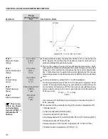
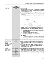
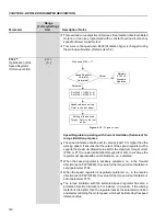
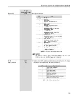
DC Link
Voltage (Ud)

P152

Speed

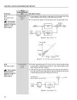
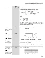
Figure 6.14

- Voltage regulation block diagram of the DC Link

Speed Ramp

Output

P151

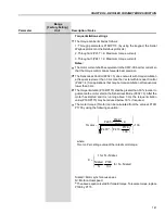
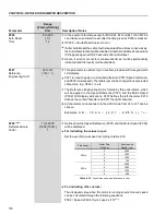
NOTE!

For large motors it’s recommended the use of the ramp holding
function.

Summary of Contents for CFW-09

Page 1: ...ur de Vitesse CFW 09 Frequentie Omzetter CFW 09 Frekvensomriktare CFW 09 Преобразователь частоты CFW 09 User s Guide Manual del Usuario Manual do Usuário Bedienungsanleitung Guide d instalation et d exploitation Installatie en gebruikshandleiding Bruksanvisning Руководство по эксплуатации Motors Automation Energy Coatings ...

Page 2: ...ENCY INVERTER MANUAL ATTENTION It is very important to check if the inverter software version is the same as indicated above 09 2008 Series CFW 09 Software version 4 0X Language English Document 0899 5306 12 ...

Page 3: ...rs Models 500 600 V Refer to items 1 to 9 8 Inclusion of the items 8 14 Modbus RTU 8 17 CFW 09 Supplied by the DC Link Line HD Refer to item 8 8 18 CFW 09 RB Regenerative Converter 8 Updating of the Spare Part List 7 9 Inclusion of new functions Overcurrent Protection Default factory reset 50 Hz Timer Relay Ramp Holding 9 New lines of the current and power supply 9 PID Regulator to Academic Changi...

Page 4: ...Mounting Specifications 43 3 1 3 1 Mounting Inside a Panel 44 3 1 3 2 Mounting on Surface 45 3 1 3 3 Mounting with the Heatsink Through a Surface 46 3 1 4 Keypad HMI and Cover Removal 48 3 2 Electrical Installation 49 3 2 1 Power Grounding Terminals 49 3 2 2 Location of the Power Grounding Control Connections 51 3 2 3 Rated Voltage Selection 53 3 2 4 Power Grounding Wiring and Fuses 54 3 2 5 Power...

Page 5: ...arameter Description 6 1 Access and Read Only Parameters P000 to P099 118 6 2 Regulation Parameters P100 to P199 124 6 3 Configuration Parameters P200 to P399 147 6 3 1 Parameters for CraneApplications and for Torque Master Slave Function P351 to P368 208 6 4 Motor Parameters P400 to P499 214 6 5 Special Functions Parameters P500 to P699 220 6 5 1 PID Regulator 220 6 5 2 Description 220 CHAPTER 7 ...

Page 6: ...4 DeviceNet 284 8 12 5 DeviceNet Drive Profile 286 8 12 6 EtherNet IP 287 8 12 7 Use to the Fieldbus Related Parameters of the CFW 09 294 8 12 7 1 Variables Read from the Inverter 294 8 12 7 2 Variables Written in the Inverter 296 8 12 7 3 Fault Indications 298 8 12 7 4 Addressing of the CFW 09 Variables in the Fieldbus Devices 299 8 13 Serial Communication 300 8 13 1 Introduction 300 8 13 2 Inter...

Page 7: ...ltiple Coils 324 8 14 3 6 Function 16 Write Multiple Registers 325 8 14 3 7 Function 43 Read Device Identification 326 8 14 4 Communication Errors 327 8 14 4 1 Error Messages 327 8 15 KIT KME for Extractable Mounting 329 8 16 CFW 09 SHARK NEMA 4X 330 8 16 1 Enclosure Specifications 330 8 16 2 Mechanical Installation 330 8 16 3 Electrical Installation 332 8 16 4 Closing the Inverter 332 8 16 5 How ...

Page 8: ...ve Open 119 1 Active Closed P013 Digital andRelay Outputs DO1 DO2 0 Inactive Dropped out 120 RL1 RL2 and RL3 Status 1 Active Picked up P014 Last Fault 0 to 71 121 P015 Second Previous Fault 0 to 71 121 P016 Third Previous Fault 0 to 71 121 P017 Fourth Previous Fault 0 to 71 121 P018 Analog Input AI1 Value 100 to 100 121 P019 Analog Input AI2 Value 100 to 100 121 P020 Analog Input AI3 Value 100 to ...

Page 9: ...0 rpm 125 P122 2 11 JOG or JOG Speed Reference 00 to P134 150 125 rpm 125 P123 2 11 JOG Speed Reference 00 to P134 150 125 rpm 125 P124 2 11 Multispeed Reference 1 P133 to P134 90 75 rpm 126 P125 2 11 Multispeed Reference 2 P133 to P134 300 250 rpm 126 P126 2 11 Multispeed Reference 3 P133 to P134 600 500 rpm 126 P127 2 11 Multispeed Reference 4 P133 to P134 900 750 rpm 126 P128 2 11 Multispeed Re...

Page 10: ... V 133 and V F Control Vector Control 585 to 800 P296 1 800 136 with optimal braking 616 to 800 P296 2 800 678 to 800 P296 3 800 739 to 800 P296 4 800 809 to 1000 P296 5 1000 885 to 1000 P296 6 1000 924 to 1000 P296 7 1000 1063 to 1200 P296 8 1200 P152 Proportional Gain 0 00 to 9 99 0 00 137 P153 6 Dynamic Braking Level 339 to 400 P296 0 375 V 137 585 to 800 P296 1 618 616 to 800 P296 2 675 678 to...

Page 11: ... 0 Ramp 0 Ramp 145 1 Step Flux Regulator P175 5 Proportional Gain 0 0 to 31 9 2 0 146 P176 5 Integral Gain 0 000 to 9 999 0 020 146 P177 Minimum Flux 0 to 120 0 146 P178 Nominal Flux 0 to 120 100 146 P179 Maximum Flux 0 to 120 120 146 P180 Field Weakenig Start Point 0 to 120 95 146 P181 1 Magnetization Mode 0 General Enable 0 General Enable 146 1 Start Stop CONFIGURATION PARAMETERS P200 to P399 Ge...

Page 12: ...0 1500 150 P209 1 Motor Phase Loss Detection 0 Off 0 Off 151 1 On P210 Decimal Point of the Speed Indication 0 to 3 0 151 P211 1 Zero Speed Disable 0 Off 0 Off 151 1 On P212 Condition to Leave Zero 0 N or N P291 0 N or N P291 152 Speed Disable 1 N P291 P213 Time Delay for Zero Speed Disable 0 to 999 0 s 152 P214 1 9 Line Phase Loss Detection 0 Off 1 On 152 1 On P215 1 Keypad Copy Function 0 Off 0 ...

Page 13: ... 6 Add AI 7 E P 8 Multispeed 9 Serial 10 Fieldbus 11 PLC P223 1 8 Local FWD REV Selection 0 Always Forward 2 Keypad 156 1 Always Reverse Default FWD 2 Keypad Default FWD 3 Keypad Default REV 4 DI2 5 Serial Default FWD 6 Serial Default REV 7 Fieldbus Default FWD 8 Fieldbus Default REV 9 Polarity AI4 10 PLC FWD 11 PLC REV P224 1 Local Start Stop Selection 0 I and O Keys 0 I and O Keys 156 1 DIx 2 Se...

Page 14: ...e JOG Selection 0 Disable 2 DI3 to DI8 157 1 Keypad 2 DI3 to DI8 3 Serial 4 Fieldbus 5 PLC Stop Model Definition P232 1 Stop Mode Selection 0 Ramp to Stop 0 Ramp to Stop 163 1 Coast to Stop 2 Fast Stop Analog Inputs P233 Analog Inputs Dead Zone 0 Off 0 Off 163 1 On P234 Analog Input AI1 Gain 0 000 to 9 999 1 000 164 P235 1 Analog Input AI1 Signal 0 0 to 10 V 0 to 20 mA 0 0 to 10 V 165 1 4 to 20 mA...

Page 15: ... 0 0 168 P245 Analog Input AI4 Gain 0 000 to 9 999 1 000 168 P246 1 Analog Input AI4 Signal 0 0 to 10 V 0 to 20 mA 0 0 to 10 V 168 Requires Optional I O Expansion 1 4 to 20 mA 0 to 20 mA Board EBA 2 10 to 0 V 20 to 0 mA 3 20 to 4 mA 4 10 to 10 V P247 Analog Input AI4 Offset 100 0 to 100 0 0 0 169 P248 Input Filter AI2 0 0 to 16 0 0 0 s 169 Analog Outputs P251 Analog Output AO1 Function 0 Speed Ref...

Page 16: ...rrent Vector 5 Output Current 6 PID Process Variable 7 Active Current V F 8 Power kW 9 PID Setpoint 10 Positive Torque Current 11 Motor Torque 12 PLC 13 Not Used 14 Motor Voltage 15 to 63 Exclusive WEG use P256 Analog Output AO3 Gain 0 000 to 9 999 1 000 170 P257 Analog Output AO4 Function 0 Speed Reference 5 Output Current 170 Requires optional I O Expansion 1 Total Reference Board EBA 2 Real Spe...

Page 17: ...erse Run P265 1 8 Digital Input DI3 Function 0 Not Used 0 Not Used 172 1 Local Remote 2 General Enable 3 JOG 4 No External Fault 5 Increase E P 6 Ramp 2 7 Not Used 8 Forward Run 9 Speed Torque 10 JOG 11 JOG 12 Reset 13 Fieldbus 14 Start 3 wire 15 Man Auto 16 Not used 17 Disables Flying Start 18 DC Voltage Regulator 19 Parameter Setting Disable 20 Load user 21 Timer RL2 22 Timer RL3 P266 1 Digital ...

Page 18: ...5 Increase E P 6 Ramp 2 7 Multispeed MS1 8 Fast Stop 9 Speed Torque 10 JOG 11 JOG 12 Reset 13 Fieldbus 14 Start 3 wire 15 Man Auto 16 Not Used 17 Disables Flying Start 18 DC Voltage Regulator 19 Parameter Setting Disable 20 Load User 21 Timer RL2 22 Timer RL3 P268 1 Digital Input DI6 Function 0 Not Used 6 Ramp 2 173 1 Local Remote 2 General Enable 3 JOG 4 No External Fault 5 Decrease E P 6 Ramp 2 ...

Page 19: ...cal Remote expansion board EBA or EBB 2 General Enable 3 JOG 4 No External Fault 5 Not Used 6 Ramp 2 7 Not Used 8 Fast Stop 9 Speed Torque 10 JOG 11 JOG 12 Reset 13 Fieldbus 14 Start 3 wire 15 Man Auto 16 Not Used 17 Disables Flying Start 18 DC Voltage Regulator 19 Parameter Setting Disable 20 Load User 21 Timer RL2 22 Timer RL3 P270 1 Digital Input DI8 Function 0 Not used 0 Not used 173 Requires ...

Page 20: ...put DO1 Function 0 Not used 0 Not Used 180 requires optional I O 1 N Nx expansion board EBA or EBB 2 N Nx 3 N Ny 4 N N 5 Zero Speed 6 Is Ix 7 Is Ix 8 Torque Tx 9 Torque Tx 10 Remote 11 Run 12 Ready 13 No Fault 14 No E00 15 No E01 E02 E03 16 No E04 17 No E05 18 4 to 20 mA OK 19 Fieldbus 20 FWD 21 Proc Var VPx 22 Proc Var VPy 23 Ride Through 24 Pre charge OK 25 Fault 26 Enabled Hours Hx 27 Not Used ...

Page 21: ...0 Remote 11 Run 12 Ready 13 No Fault 14 No E00 15 No E01 E02 E03 16 No E04 17 No E05 18 4 to 20 mA OK 19 Fieldbus 20 FWD 21 Proc Var VPx 22 Proc Var VPy 23 Ride Through 24 Pre charge OK 25 Fault 26 Enabled Hours Hx 27 Not Used 28 Not Used 29 N Nx and Nt Nx 30 Brake Actual Speed 31 Brake Total Reference 32 Overweight 33 Slack Cable 34 Torque Polarity 35 Torque Polarity 36 F Fx _ 1 37 F Fx _ 2 38 Se...

Page 22: ... No E00 15 No E01 E02 E03 16 No E04 17 No E05 18 4 to 20 mA OK 19 Fieldbus 20 FWD 21 Proc Var VPx 22 Proc Var VPy 23 Ride Through 24 Pre charge OK 25 Fault 26 Enabled Hours Hx 27 PLC 28 Not Used 29 N Nx and Nt Nx 30 Brake Actual Speed 31 Brake Total Reference 32 Overweight 33 Slack Cable 34 Torque Polarity 35 Torque Polarity 36 F Fx _ 1 37 F Fx _ 2 38 Set Point Process Variable 39 No E32 40 Ready ...

Page 23: ...c Var VPx 22 Proc Var VPy 23 Ride Through 24 Pre charge OK 25 Fault 26 Enabled Hours Hx 27 PLC 28 Timer 29 N Nx and Nt Nx 30 Brake Actual Speed 31 Brake Total Reference 32 Overweight 33 Slack Cable 34 Torque Polarity 35 Torque Polarity 36 F Fx _ 1 37 F Fx _ 2 38 Set Point Process Variable 39 No E32 40 Ready 2 P280 1 Relay Output RL3 Function 0 Not used 1 N Nx 180 1 N Nx 2 N Nx 3 N Ny 4 N N 5 Zero ...

Page 24: ...P283 Time for RL2 ON 0 0 to 300 0 0 s 186 P284 Time for RL2 OFF 0 0 to 300 0 0 s 186 P285 Time for RL3 ON 0 0 to 300 0 0 s 186 P286 Time for RL3 OFF 0 0 to 300 0 0 s 186 Nx Ny Ix Zero Speed Zone N N and Tx P287 Hysteresis for Nx Ny 0 0 to 5 0 1 0 193 P288 2 11 Nx Speed 0 to P134 120 100 rpm 193 P289 2 11 Ny Speed 0 to P134 1800 1500 rpm 193 P290 7 Ix Current 0 to 2 0 x P295 1 0 x P295 A 193 P291 Z...

Page 25: ... A 82 1468 A 39 2 9 A 40 4 2 A 4 7 A 6 10 A 41 12 A 42 14 A 43 22 A 44 27 A 45 32 A 46 44 A 47 53 A 48 63 A 49 79 A 25 600 A 72 652 A 73 794 A 76 897 A 78 978 A 79 1191A 81 1345 A 51 107 A 53 147 A 55 211 A 57 247 A 60 315 A 62 343 A 63 418 A 65 472 A 50 107 A 52 127 A 54 179 A 56 225 A 58 259 A 59 305 A 61 340 A 64 428 A 68 492 A 70 580 A 71 646 A 74 813 A 75 869 A 77 969 A 80 1220 A 38 2 A 66 33...

Page 26: ...P133 to P134 600 rpm 197 P304 Skip Speed 2 P133 to P134 900 rpm 197 P305 Skip Speed 3 P133 to P134 1200 rpm 197 P306 Skip Band 0 to 750 0 rpm 197 Serial Communication P308 1 Inverter Address 1 to 30 1 198 P309 1 Fieldbus 0 Disable 0 Disable 198 1 Profibus DP DP V1 2 I O 2 Profibus DP DP V1 4 I O 3 Profibus DP DP V1 6 I O 4 DeviceNet 2 I O 5 DeviceNet 4 I O 6 DeviceNet 6 I O 7 EtherNet IP 2 I O 8 E...

Page 27: ...ng Start Ride Through P320 1 Flying Start Ride Through 0 Inactive 0 Inactive 200 1 Flying Start 2 Flying Start Ride Through 3 Ride Through P321 6 Ud Line Loss Level 178 to 282 P296 0 252 V 200 307 to 487 P296 1 436 324 to 513 P296 2 459 356 to 564 P296 3 505 388 to 615 P296 4 550 425 to 674 P296 5 602 466 to 737 P296 6 660 486 to 770 P296 7 689 559 to 885 P296 8 792 P322 6 Ud Ride Through 178 to 2...

Page 28: ...n P351 1 Delay for E33 0 0 to 99 9 99 9 s 208 P352 1 Delay for E34 0 to 999 999 s 208 P353 1 Delay for N Nx Brake Activation 0 0 to 20 0 0 0 s 208 P354 1 Delay for Resetting the Integrator 0 0 to 10 0 2 0 s 208 of the Speed Regulator P355 1 Delay for Accepting New 0 0 to 10 0 1 0 s 208 Start Stop Commands P356 1 Delay for Ramp Enable 0 0 to 10 0 0 0 s 209 Indication of the Torque Current Polarity ...

Page 29: ... P403 1 11 Motor Rated Frequency 0 to 300 P202 0 1 2 and 5 60 50 Hz 214 30 to 120 P202 3 and 4 P404 1 Motor Rated hp 0 0 33 hp 0 25 kW 4 1 5 hp 1 1 kW 214 1 0 50 hp 0 37 kW 2 0 75 hp 0 55 kW 3 1 0 hp 0 75 kW 4 1 5 hp 1 1 kW 5 2 0 hp 1 5 kW 6 3 0 hp 2 2 kW 7 4 0 hp 3 0 kW 8 5 0 hp 3 7 kW 9 5 5 hp 4 0 kW 10 6 0 hp 4 5 kW 11 7 5 hp 5 5 kW 12 10 0 hp 7 5 kW 13 12 5 hp 9 0 kW 14 15 0 hp 11 0 kW 15 20 0...

Page 30: ...07 1 2 Motor Rated Power Factor 0 50 to 0 99 216 Measured Parameters P408 1 Self Tuning 0 No 0 No 216 1 No Rotation 2 Run for Imr 3 Run for Tm 4 Estimate Tm P409 1 Motor Stator Resistance Rs 0 000 to 77 95 0 000 217 P410 Motor Magnetizing Current Imr 0 0 to 1 25 x P295 0 0 A 218 P411 1 Motor Flux Leakage Inductance LS 0 00 to 99 99 0 00 mH 218 P412 LR RR Constant Rotor Time 0 000 to 9 999 0 000 s ...

Page 31: ...inverter disabled motor stopped 2 Values may change as a function of the Motor Parameters 3 Values may change as a function of P413 Tm Constant obtained during Self tuning 4 Values may change as a function of P409 and P411 obtained during Self tuning 5 Values may change as a function of P412 Tr Constant obtained during Self tuning 6 Values may change as a function of P296 7 Values may change as a ...

Page 32: ...0 E31 Keypad Connection Fault 230 E32 Motor Overtemperature 230 E33 Speed without control 230 E34 Long period at torque limitation 230 E41 Self Diagnosis Fault 230 E70 Internal DC Supply Undervoltage 231 E71 PLC Watchdog Error 231 E04 can be Pre charge Circuit Failure only in the following models 86 A 380 480 V 70 A 220 230 V 44 A 500 600 V and for all 500 690 V and 660 690 V models E04 can also o...

Page 33: ...ENCE 34 III Other Messages Display Description rdy Inverter is Ready to be Enabled run Inverter is Enabled Sub Power Supply Voltage is Too Low for the Inverter Operation Undervoltage dCbr Inverter in DC Braking Mode Refer to P300 ...

Page 34: ...standing of operation and proper performance of the equipment The following symbols may be attached to the product serving as Safety Notice High Voltages Components are sensitive to electrostatic discharge Do not touch them without following proper grounding procedures Mandatory connection to ground protection PE Shield connection to ground DANGER Only qualified personnel should plan or implement ...

Page 35: ...tes for the total discharge of the power capacitors Always connect the frame of the equipment to the ground PE at the suitable connection point ATTENTION All electronic boards have components that are sensitive to electrostatic discharges Never touch anyof the electrical components or connectors without following proper grounding procedures If necessary to do so touch the properly grounded metalli...

Page 36: ...plied in several ways it is impossible to describe here all of the application possibilities WEG does not accept any responsibility when the CFW 09 is not used according to this Manual No part of this Manual may be reproduced in any form without the written permission of WEG It is important to note the Software Version installed in the Version CFW 09 since it defines the functions and the programm...

Page 37: ...nput 2x14bitanal outputs B 1 isola 4 to 20 mA In 2 isola 4 to 20 mA out 2 digital outputs 1 encoder In Out 1 PTC input External Control Analog Outputs AO1 AO2 Relay Outputs RL1 RL3 Keypad remote DC Link Feedbacks voltage current PE PE Modbus RTU Figure 2 1 CFW 09 block diagram Human Machine Interface The Sensorless Vector Control permits high torques and quick response even at very low speeds and ...

Page 38: ...on of the CFW 09 Nameplate FRONTVIEW VIEW A Figure 2 2 CFW 09 identification Nominal Output Current and Switching Frequency for VT and CT Loads Nominal Output Data Voltage Frequency CFW 09 Model Serial Number WEG Part Number Nominal Input Data Phase Current and Frequency Software Revision ...

Page 39: ... 7 A 0010 10 A 0012 12 A 0014 14 A 0022 22 A 0027 27 A 0032 32 A 0044 44 A 0053 53 A 0063 63 A 0079 79 A 500 690 V 0107 107 A 0147 147 A 0211 211 A 0247 247 A 0315 315 A 0343 343 A 0418 418 A 0472 472 A 660 690 V 0100 100 A 0127 127 A 0179 179 A 0225 225 A 0259 259 A 0305 305 A 0340 340 A 0428 428 A Note For rated output current specification of variable torque VT refer to chapter 9 The rated outp...

Page 40: ... up to size 3 refer to item 9 and for models above the packing will be with wood pallet and wood box The outside of the packing container has a nameplate that is identical to that on the CFW 09 Please check if the nameplate data matches the ordered ones The boxes up to size 7 must be placed and opened on a table sizes above 3 with the help of two persons Open the box remove the cardboard or expand...

Page 41: ...ºC to 40 ºC 32 ºF to 104 ºF nominal conditions From 40 ºC to 55 ºC 104 ºF to 131 ºF with 2 current derating for each 1 ºC 33 8 ºF degree above 40 ºC 104 ºF Relative Air Humidity 5 to 90 non condensing Maximum Altitude 1000 m 3 300 ft nominal conditions From 1000 m to 4000 m 3 300 ft to 13 200 ft with 1 current reduction for each 100 m 330 ft above 1000 m 3 300 ft Pollution Degree 2 according to EN...

Page 42: ...53 Size 9 1020 688 492 275 985 69 15 M10 216 IP20 39 37 27 56 19 33 10 83 37 99 2 95 0 59 3 8 476 2 Size 10 1185 700 492 275 1150 69 15 M10 259 46 65 27 56 19 33 10 83 45 27 2 95 0 59 3 8 571 Size 10E 1185 700 582 275 1150 69 15 M10 310 46 65 27 56 22 91 10 83 45 27 2 95 0 59 3 8 682 Table 3 1 Installation data Refer to item 9 1 For installing the CFW 09 leave at least the minimum free spaces arou...

Page 43: ... boxes adequate cooling is required to ensure that the temperature around the inverter will not exceed the maximum allowed temperature Refer to Dissipated Power in item 9 1 For reference table 3 3 shows the cooling airflow for each inverter model 3 1 3 1 Mounting Inside a Panel ATTENTION When inverters are installed side by side maintain the minimum recommended distance B When inverters are instal...

Page 44: ... 600 V 70 A and 86 A 220 230 V 60 A and 70 A 380 480 V 105 A and 130 A 220 230 V 86 A and 105 A 380 480 V 44 A to 79 A 500 600 V 142 A 380 480 V 180 A to 240 A 380 480 V 107 A to 211 A 500 690 V 100 A to 179 A 660 690 V 312 A and 361 A 380 480 V 450 A to 600 A 380 480 V 247 A to 472 A 500 690 V 225 A to 428A 660 690 V Table 3 3 Cooling air flow requirements Figure 3 3 shows the installation of the...

Page 45: ...rough the mounting plate as shown in figure 3 4 In this case refer to installation drawings shown in figure 3 4 c and maintain the distances indicated in table 3 4 NOTE When installing the heatsink through the mounting surface according to figure 3 4 the degree of protection behind this surface is NEMA 1 IP20 NEMA1 rating does not protect against dust and water 3 1 3 3 Mounting with the Heatsink T...

Page 46: ...e CFW 09 with the heatsink through the mounting surface a Sizes 1 and 2 Step3 Step 1 Step 2 Air Flow 4 mm 1 6 in max Step 2 Step 3 Step 1 Air Flow 4 mm 1 6 in max Sizes 1 and 2 Sizes 3 to 8 b Sizes 3 to 8E c Cutout Dimensions Refer to table 3 4 Kit KMF Top Support Kit KMF BottonSupport ...

Page 47: ... 417102516 13 27 20 75 7 87 21 85 2 70 0 59 0 35 Size 6 13 27 652 200 680 68 5 14 10 417102517 13 27 25 67 7 87 26 77 2 70 0 59 0 39 Size 7 337 812 200 840 68 5 14 10 417102518 13 27 31 97 7 87 33 07 2 70 0 59 0 39 Size 8 412 952 275 980 68 5 14 10 417102519 16 22 37 48 10 38 38 58 2 70 0 59 0 39 Size 8E 412 1122 275 1150 68 5 14 10 16 22 44 17 10 83 45 27 2 70 0 59 0 39 The Through Surface Mounti...

Page 48: ...gency stop device Provide another devices for this function The power connection terminals can be of different sizes and configurations depending on the inverter model as shown in figure 3 6 Terminals R S T AC supply line Models up to 10 A at 220 230 V can be operated with two phases single phase operation without current derating In this case the AC supply can be connected to any 2 of the 3 input...

Page 49: ...models b Size 2 models c Size 3 4 and 5 models d Size 6 and 7 220 230 V and 380 480 V models g Size 9 and 10 380 480 V models f Size 8 380 480 V models e Size 7 500 600 V models h Size 8E 500 690 V and 660 690 V models Figure 3 6 a to h Power terminals ...

Page 50: ... 3 6 i Power terminals 3 2 2 Location of the Power Grounding Control Connections GROUNDING POWER CONTROL a Size 1 and 2 models b Size 3 4 and 5 models Note No voltage selection needed for these models Figure 3 7 a and b Location of the power grounding control connections and rated voltage ...

Page 51: ...els RATED VOLTAGE SELECTION CONTROL GROUNDING GROUNDING RATED VOLTAGE SELECTION GROUNDING e Size 9 and 10 models d Size 8 models CONTROL CONTROL POWER POWER POWER RATED VOLTAGE SELECTION g Size 10E GROUNDING POWER CONTROL RATED VOLTAGE SELECTION f Size 8E GROUNDING CONTROL RATED VOLTAGE SELECTION POWER AUXILIARY CIRCUITFUSES AUXILIARY CIRCUITFUSES ...

Page 52: ... for models 180A from position XC60 440 460 V and insert it on the proper position according to the application line voltage 500 600 V models Remove jumper on the LVS2 board from position XC62 550 V 575 V 600 V and insert it on the proper position according to the line voltage 500 690 V models Remove jumper on the CIP3 board from position XC62 550 V 575 V 600 V and insert it on the proper position...

Page 53: ...ipment PLCs temperature controllers thermocouples etc and its wiring must stay at a minimum distance of 10 in 0 25 m from the frequencyinverters the reactors and from the input and motor power cables ATTENTION When flexible wires are used for power and grounding connections it is necessary to provide appropriate crimp terminals Use wire sizing and fuses as recommended in table 3 5 3 2 4 Power Grou...

Page 54: ...2x4 0 2x150 2x250 2x120 2x4 0 2x120 2x4 0 2x150 2x250 2x150 2x250 2x150 2x250 2x150 2x250 3x120 3x4 0 2x150 2x250 3x120 3x4 0 3x150 3x250 Grounding Cables mm2 AWG MCM CT VT 2 5 12 2 5 12 2 5 12 2 5 12 2 5 12 2 5 12 2 5 12 2 5 12 2 5 12 2 5 12 2 5 12 2 5 12 2 5 12 2 5 12 2 5 12 2 5 12 4 0 10 2 5 12 4 0 10 4 0 10 4 0 10 6 0 8 4 0 10 4 0 10 6 0 8 16 6 6 0 8 6 0 8 16 6 16 6 16 6 16 6 16 6 16 6 16 6 16...

Page 55: ... V 60 A to 86 A 380 480 V 105 A to 130 A 220 230 V 105 A to 142 A 380 480 V 44 A to 79 A 500 600 V 180 A to 240 A 380 480 V 312 A to 600 A 380 480 V 107 A to 472 A 500 690 V 100 A to 428 A 660 690 V Power Cables N m Ibf in 1 76 15 58 2 00 17 70 1 40 12 30 1 40 12 30 3 00 26 10 15 50 132 75 30 00 265 50 60 00 531 00 Line Fuses For protecting the input rectifier diodes and the wiring use UR Type Ult...

Page 56: ...rter power section The drive is designed to use control signals for starting and stopping the motor If used the input device must not exceed one operation every 6 minutes otherwise the inverter may be damaged ATTENTION Set jumper to select the rated line voltage 380 480 V for inverters 86Aor higher Refer to item 3 2 3 NOTE TheAC input voltage must be compatible with the inverter rated voltage Supp...

Page 57: ...it Use twisted cable for the connection between inverter and DB resistor Provide physical separation between this cable and the signal and control cables When the DB resistor is mounted inside the panel consider the watt loss generated when the enclosure size and ventilation required are calculated DANGER Inverters must be grounded for safety purposes PE The earth or ground connection must complyw...

Page 58: ... remove the jumper as shown in figure 3 11 In 500 600 V 500 690 V 660 690 V models the jumper is accessible taking out models 2 9 A to 14 A 500 600 V or opening models 22 A to 79 A 500 600 V 107 A to 211 A 500 690 V and 100 A to 179 A 660 690 V the front cover or taking out the connections cover 247Ato 472A 500 600 V and 225A to 428 A 660 690 V In models 180 A to 600 A 380 480 V besides opening or...

Page 59: ...works remove the jumper a Models 180 A to 240 A 380 480 V b Models 312 A to 600 A 380 480 V J8 jumper position X11 Grounded network X9 IT network c Models 2 9 A to 14 A 500 600 V d Models 22 A to 32 A 500 600 V e Models 44 A to 79 A 500 600 V f Models 107 A to 211 A 500 600 V and 100 A to 179 A 660 690 V For IT networks remove the jumper For IT networks remove the jumper For IT networks remove the...

Page 60: ...Outputs Factory Default Function Relay Output No Fault Relay Output Speed P288 N Nx Relay Output No Fault Relay Output Speed P288 N Nx Relay Output Speed Reference P288 N Nx Terminal XC1 1 DI1 2 DI2 3 DI3 4 DI4 5 DI5 6 DI6 7 COM 8 COM 9 24 Vdc 10 GND 11 REF 12 AI1 13 AI1 14 REF 15 AI2 16 AI2 17 AO1 18 GND AO1 19 AO2 20 GND AO2 Terminal XC1A 21 RL1 NC 22 RL1 NO 23 RL2 NO 24 RL1 C 25 RL2 C 26 RL2 NC...

Page 61: ...5 6 DI6 7 COM 8 COM 9 24 Vdc 10 GND 11 REF 12 AI1 13 AI1 14 REF 15 AI2 16 AI2 17 AO1 18 GND AO1 19 AO2 20 GND AO2 Terminal XC1A 21 RL1 NC 22 RL1 NO 23 RL2 NO 24 RL1 C 25 RL2 C 26 RL2 NC 27 RL3 NO 28 RL3 C Specifications 6 Isolated Digital Inputs Minimum High Level 18 Vdc Maximum Low Level 3 Vdc Maximum Voltage 30 Vdc Input Current 11 mA 24 Vdc Isolated 24 Vdc 8 Capac 90 mA Grounded by a 249 resist...

Page 62: ...on If the crossing of these cables is unavoidable install them perpendicular maintaining a minimum separation distance of 5 cm 2 in at the crossing point Can be used for grounding of the signal and control cable shields CC9 Board Wiring Length 100 m 330 ft 100 m 330 ft 30 m 100 ft 30 m 100 ft Min Separation Distance 10 cm 4 in 25 cm 10 in 10 cm 4 in 25 cm 10 in Inverter Model Output current 24 A O...

Page 63: ...en them Connection 1 Keypad Start Stop Local Mode With the factory default setting you can operate the inverter in the local mode This operation mode is recommended for users who are operating the inverter for the first time without additional control connections For start up according to this operation mode follow chapter 5 3 2 7 Typical Terminal Connections Connect the shield as shown in figure ...

Page 64: ... via DI2 Set P223 4 if in Local Mode or Set P226 4 if in Remote Mode S1 and S2 are momentary push buttons NO contact for Start and NC contact for Stop The speed reference can be viaAnalog InputAI as in Connection 2 via keypad HMI as in Connection 1 or via any other source The function Start Stop is described in chapter 6 in this manual Connector XC1 1 DI1 2 DI2 3 DI3 4 DI4 5 DI5 6 DI6 7 COM 8 COM ...

Page 65: ...h local and remote operation modes At the same time the keys and remain inactive even when P224 0 or P227 0 The direction of rotation is defined automatically by the FWD Run REV Run commands Clockwise rotation for Forward and Counter Clockwise rotation for Reverse The speed reference can be from any source as in Connection 3 Figure 3 17 XC1 CC9 wiring for connection 4 Connector XC1 1 DI1 2 DI2 3 D...

Page 66: ...or public network which does not supply buildings used for domestic purpose second environment according to the EN61800 3 standard The filters specified in items 3 3 2 and 3 3 3 do not apply to the 500 600 V models For installing the frequency inverters in accordance to the Product Standard EN61800 3 the following items are required 1 Output cables motor wiring must be flexible armored or to be in...

Page 67: ...ch a network Description of conducted emission classes according to the standard EN61800 3 Class B first environment unrestricted distribution Class A1 first environment restricted distribution Class A2 second environment unrestricted distribution 3 3 2 Epcos Filters The following tables 3 9 3 10 and 3 11 show the Epcos filters for CFW 09 frequency inverters with 380 480 V 500 600 V and 660 690 V ...

Page 68: ...3 A CT VT B84143A16R105 First environment restricted distribution 16 A CT VT B84143A25R105 First environment restricted distribution 24 A CT VT N A 100 m 35 m First environment restricted distribution CT B84143A36R105 30 A VT 85 m First environment restricted distribution CT B84143A50R105 38 A 3 VT First environment restricted distribution CT 45 A 3 VT B84143A66R105 100 m 50 m NO First environment...

Page 69: ...mits Note Minimum output frequency 2 4 Hz Maximum motor cable length according to conducted emission class EN61800 3 Inverter Model Load Type Epcos Input Filter Class A2 Class A1 Class B Inside metallic panel Electromagnetic radiation disturbance level Product Standard EN61800 3 1996 A11 2000 CT 100 A 660 690 V and 107 A 500 690 V VT First environment restricted distribution CT B84143B150S21 127 A...

Page 70: ...232 EBA RS 485 Serial Interface EBA RS 485 Serial Interface No No EBB RS 485 Serial Interface No No Model Optional Device Input filter Input CM Choke Output CM Choke No No No No No No No No No No No No No Yes No No Inside Metallic Panel Electromagnetic radiation disturbance level Product Standard EN61800 3 1996 A11 2000 1 Conducted Emission Class 2 B B B B B A1 A1 A1 380 480 V power supply First e...

Page 71: ...tion First environment restricted distribution First environment restricted distribution 2 x Schaffner 203 1151 042 filter input output sides 2 x Schaffner 203 1151 042 filter input output sides Schaffner 203 1151 042 2 turns in the control cable 2 x Schaffner 203 1151 042 filter input output sides No 2 X Schaffner 203 1151 042 Output filter side 2 X Schaffner 167 1151 043 output filter side Schaf...

Page 72: ...No No No No No No No No No 2 X Schaffner 203 1151 042 UVW 2 X Schaffner 203 1151 042 UVW 2 X Schaffner 167 1151 043 UVW No No No Yes No No No No Yes Yes Yes Yes Inside Metallic Panel Conducted Emission Class 2 B B B A1 A1 A1 A1 A1 A1 A1 A1 A1 First environment restricted distribution First environment restricted distribution First environment restricted distribution First environment restricted di...

Page 73: ...320 21 21 0208 2137 B84143B400S20 400 33 21 j 0208 2138 B84143B600S20 600 57 22 k 0208 2139 B84143B1000S20 1000 99 28 l 0208 2140 B84143B150S21 150 12 13 0208 2141 B84143B180S21 180 14 13 m 0208 2142 B84143B250S21 250 14 15 n 0208 2143 B84143B400S125 400 33 21 o 0208 2144 B84143B600S125 Epcos 600 57 22 p 0208 2075 FN3258 7 45 7 3 8 0 5 45 0208 2076 FN3258 16 45 16 6 0 8 45 0208 2077 FN3258 30 47 3...

Page 74: ... b EMC filters for CFW 09 inverter series dimensions in mm b EPCOS B84143A16R105 Filter PE M4 x 11 133 7 8 Terminals 4 mm L1 L2 L3 Marking LINE LOAD 155 165 L1 L2 L3 50 38 51 4 4 5 6 3 1 5 PE M5 x 15 L1 L2 L3 L1 L2 L3 LINE LOAD Marking 38 4 5 1 5 70 199 5 Terminals 4 mm 221 231 9 60 46 4 ...

Page 75: ...C filters for CFW 09 inverter series dimensions in mm d EPCOS B84143A36R105 and B84143A50R105 Filter PE M5 x 15 L1 L2 L3 L1 L2 L3 LINE LOAD Marking 38 4 5 1 5 83 199 5 PE M6 x 14 221 231 9 60 46 4 PE M6 x 14 L1 L2 L3 L1 L2 L3 LINE LOAD Marking 35 4 5 1 5 90 200 Terminals 10 mm 255 265 8 70 58 ...

Page 76: ...Filter Figure 3 20 e and f EMC filters for CFW 09 inverter series dimensions in mm Terminals 35 mm Terminals 16 mm PE M6 x 14 L1 L2 L3 L1 L2 L3 LINE LOAD Marking 35 4 5 1 5 141 5 200 255 265 8 58 120 PE M10 x 34 L1 L2 L3 L1 L2 L3 LINE LOAD Marking 1 5 4 6 240 290 255 25 135 100 6 5 60 63 80 13 ...

Page 77: ...s for CFW 09 inverter series dimensions in mm Terminals 35 mm PE M10 x 34 L1 L2 L3 L1 L2 L3 LINE LOAD Marking 1 5 240 290 255 25 150 6 5 65 63 90 13 46 100 PE M10 x 35 L1 L2 L3 LINE LOAD Marking 6 5 0 5 350 L3 200 100 40 78 Terminal blocks 50mm2 380 365 0 5 86 65 0 3 Litz wire markings Wire end ferrule 500 10 Litz wire L2 L1 P E 90 ...

Page 78: ...er series dimensions in mm PE M10 x 35 L1 L2 L3 LINE LOAD Marking 6 5 0 5 400 L3 220 110 30 79 430 415 0 5 106 85 0 3 Litz wire markings 500 10 Litz wire L2 L1 P E 110 Terminal blocks 95 mm2 Wire end ferrule PE M10 x 30 L3 LINE Marking 25 120 60 220 260 360 2 16 85 0 5 4 x M6 mm deep 36 300 60 240 1 235 1 L2 L1 LOAD L2 L1 12 15 15 42 2 11 42 2 2 116 30 180 0 5 210 91 ...

Page 79: ...ies dimensions in mm LINE Marking 30 30 350 5 L3 15 12 410 2 5 260 235 1 91 4 x M6 mm deep 290 1 60 42 3 L2 L1 42 3 L3 L2 L1 LOAD PE M10 x 30 15 60 120 85 0 5 116 16 2 180 0 5 210 36 11 LINE Marking 40 40 350 8 L3 20 12 420 2 5 300 275 1 141 290 1 65 52 3 L2 L1 52 3 L3 L2 L1 LOAD PE M12 x 30 20 65 135 0 8 166 16 2 5 220 0 8 250 61 14 160 4 x M6 6 mm deep ...

Page 80: ...OS B84143B150S21 and B84143B180S21 Filters LINE Marking 30 20 260 3 L3 10 9 170 155 2 91 150 32 1 97 5 L2 L1 97 2 L3 L2 L1 LOAD 10 141 81 2 120 140 36 80 32 1 115 0 2 310 2 6 6 PE M10 x 30 2 x M5 mm deep LINE Marking 30 25 300 5 L3 15 11 190 165 91 60 L2 L1 L3 L2 L1 LOAD 116 2 110 140 36 80 60 42 1 360 2 PE M10 x 30 240 0 6 12 42 1 15 2 x M6 6 mm deep ...

Page 81: ...TALLATION AND CONNECTION o EPCOS B84143B400S125 Filter Figure 3 20 o EMC filters for CFW 09 inverter series dimensions in mm 40 3 15 11 L1 25 330 2 210 0 5 15 9 40 3 L2 L3 5 270 3 L3 L2 L1 220 1 240 116 100 200 78 2 2 ...

Page 82: ...STALLATION AND CONNECTION p EPCOS B84143B600S125 Filter Figure 3 20 p EMC filters for CFW 09 inverter series dimensions in mm 39 3 15 11 L1 30 370 2 240 1 15 39 3 L2 L3 8 310 3 L3 L2 L1 265 3 90 140 120 250 0 5 215 12 ...

Page 83: ...m2 or AWG 1 0 Max Torque 8 Nm Type 45 Terminal block for 6 mm2 solid cable 4 mm2 flexible cableAWG 12 Type 47 Terminal block for 16 mm2 solid wires 10 mm2 flexible wires AWG8 Type 52 Dimesions in mm inch Terminal block for 25 mm2 solid wires 16 mm2 flexible wires AWG 6 FRONTVIEW MECHANICALDATASIDE VIEW Connector Rated Current Top Figure 3 20 q EMC filters for CFW 09 inverter series dimensions in m...

Page 84: ...00 A to 1000 A Type 28 M10 bolt Top Bus bar connection Type 99 Series FN 2259 These filters are supplied with M12 bolts for the grounding connection Top Connector RATED CURRENT Figure 3 20 r EMC filters for CFW 09 inverter series dimensions in mm NOTE The declaration of conformityCE is available on the website www weg net or on the CD which comes with the products ...

Page 85: ...the fault codes inverter status the parameter number and its value For units of current voltage or frequency the LED display shows the unit in the right side digit L S D as shown here A current A U voltage V H frequency Hz Blank speed and other parameters NOTE When the indication is higher than 9999 for instance in rpm the number corresponding to the ten of thousand will not be displayed ex 12345 ...

Page 86: ...gh these units at each touch of the Start key in the order shown here refer to item 4 2 2 a Stops disables the inverter via deceleration ramp Also resets the inverter after a fault has occurred Toggles the LED displaybetween the parameter number and its value Number Value Increases the speed the parameter number or the parameter value Decreases the speed the parameter number or the parameter value...

Page 87: ...nd or P227 0 I O Key for Remote Mode Starts inverter via Acceleration Ramp Stops the inverter via Deceleration Ramp NOTE It resets the inverter after a Fault Trip always active When the Jog key is pressed it accelerates the motor according to the Acceleration Ramp up to the JOG speed programmed in P122 default is 150 rpm When released the motor decelerates according to the Deceleration Ramp and st...

Page 88: ...005 Motor Frequency 1 P003 Motor Current 2 P002 Motor Speed 3 P007 Output Voltage 4 P006 Inverter Status 5 P009 Motor Torque 6 P070 motor speed and motor current 7 P040 PID process variable Table 4 1 Choosing the initial monitoring parameter NOTE Reference Backup The last frequency Reference set by the keys and is stored when the inverter is stopped or the AC power is removed provided P120 1 Refer...

Page 89: ...s are made through the parameters The parameters are shown on the display with the letter P followed by a number Example P101 101 Parameter Number De cel Time P101 10 0 s VFD ready Each parameter is associated to a numerical value parameter content that corresponds to an option selected among those options that are available for this parameters The values of the parameters define the inverter prog...

Page 90: ...iately after it has been set For the parameters that can be changed only with motor stopped the inverter will use this new set value only after the key is pressed 2 By pressing the key after the reprogramming the new programmed value will be stored automatically and will remain stored until a new value is programmed 3 If the last value programmed in the parameter is not functionally compatible wit...

Page 91: ...nd without DIx General Enable 13 P220 1 and P227 1 and without DIx Start Stop or Fast Stop and without DIx General Enable 14 DIx START and DIx STOP but P224 1 and P227 1 15 Two or more parameters between P265 or P266 or P267 or P268 or P269 and P270 equal to 15 MAN AUT 16 Two or more parameters between P265 or P266 or P267 or P268 or P269 and P270 equal to 17 Disables Flying Start 17 Two or more p...

Page 92: ...lly sets the additional parameters used for the correct operation under this control mode 5 Uncouple the load from the motor If the motor cannot be uncoupled make sure that the direction of rotation FWD REV cannot cause damage to the machine 6 Close the inverter cover or cabinet doors After the inverter has been checked AC power can be applied 1 Check the supply voltage Measure the line voltage an...

Page 93: ...age select the language 1 English Press the key to save the selected option and exit the Exit the programming mode programming mode Inverter Rated Voltage Selection 0 220 V 230 V 1 380 V Press the key to go to the 2 400 V 415 V next parameter 3 440 V 460 V 4 480 V 5 500 V 525 V 6 550 V 575 V 7 600 V 8 660 V 690 V Press the key to enter the Enter the programming mode programming mode language P20 1...

Page 94: ...ter Press the key to enter the programming mode Use the and keys to set the correct motor rated voltage value Press the key to save the programmed value and exit the programming mode Press the key to go to the next parameter Press the key to enter the programming mode Moto r Rated Volt P400 440 V Motor R ated Cur P401 9 0 A Use the and keys to select the inverter power supplyvoltage VFD Rated Volt...

Page 95: ...ve the programmed value and exit the programming mode Press the key to go to the next parameter Press the key to enter the programming mode Programmed Motor Rated Current 7 9 A Exit the programming mode Motor Rated Frequency Range 0 to 300 Hz Enter the programming mode Programmed Motor Rated Frequency 60 Hz Exit the programming mode Motor Rated rpm Range 0 to 18000 rpm Enter the programming mode M...

Page 96: ...mode Press the key to go to the next parameter Press the key to enter the programming mode Programmed Motor Rated rpm 1730 rpm Exit the programming mode Motor Rated hp Range 1 to 1600 0 hp 1 to 1190 0 kW Enter the programming mode Selected Motor Rated Power 5 0 hp 3 7 kW Exit the programming mode Motor Ventilation Type Selection 0 Self Ventilated 1 Separate Ventilation 3 Increased Protection Enter...

Page 97: ...ow the previous procedures and also set parameter P297 to 2 5 kHz 5 3 START UP This item describes the start up procedure when operating via the Keypad HMI Four types of control will be considered V F 60 Hz Sensorless Vector Vector with Encoder Feedback and VVW Voltage Vector WEG DANGER Even after the AC input is disconnected high voltages may still be present Wait at least 10 minutes after poweri...

Page 98: ...ess Vector 4 Vector with Encoder 5 VVW VFD ready Parameter Access P000 0 Parameter Access P000 0 Type of control P202 V F 60 Hz Parameter Access P000 5 Parameter Access P000 5 5 3 1 Type of Control V F 60 Hz Operation Via Keypad HMI The V F or Scalar Control is recommended in the following cases Several motors driven by the same inverter Motor rated current lower than 1 3 of the inverter rated cur...

Page 99: ... Type of control P202 V F 60 Hz ACTION LED DISPLAY DESCRIPTION LCD DISPLAY This is a read only parameter Motor accelerates from 0 to 90 rpm Minimum Speed in the Forward CW direction of rotation 1 for 4 pole motors Motor accelerates up to 1800 rpm 2 for 4 pole motors Motor decelerates 3 down to 0 rpm and then reverses the direction of rotation accelerating back up to 1800 rpm Press the key Press th...

Page 100: ...value before enabling the inverter change parameter P121 Keypad Reference OBSERVATIONS 1 If the rotation direction of the motor is not correct switch off the inverter Wait 10 minutes to allow a complete discharge of the capacitors and then swap any two wires at the motor output 2 If the acceleration current becomes too high specially at low frequencies 15 Hz adjust the Torque Boost at P136 Increas...

Page 101: ...is a higher immunity to sudden AC input voltage variation and load changes thus avoiding nuisance tripping due to overcurrent The adjustments necessary for a good sensorless control operation are made automatically The Vector Control with Encoder Feedback offers the same advantages as the Sensorless Control described above with the following additional benefits Torque and speed control down to zer...

Page 102: ...tor with Encoder Password value factory default 5 Exit the programming mode Type of Control Selection 0 V F 60 Hz 1 V F 50 Hz 2 V F Adjustable 3 Sensorless Vector 4 Vector with Encoder 5 VVW Enter the programming mode Use the and keys to set the password value Press the key to save the programmed value and exit the programming mode Press the keys or until P202 is reached Press the key to enter the...

Page 103: ...r changing to Vector Control Mode Press the key and use the and keys to set the correct motor rated voltage value Press the key to save the programmed value and exit the programming mode Press the key to go to the next parameter Press the key to enter the programming mode Use the and keys to set the correct motor rated current value Press the key to save the programmed value and exit the programmi...

Page 104: ...y to save the programmed value and exit the programming mode Press the key to go to the next parameter Enter the programming mode Programmed Motor Rated Frequency 60 Hz Exit the programming mode Motor Rated rpm Range 0 to 18000 rpm Enter the programming mode Programmed Motor Rated rpm 1730 rpm Exit the programming mode Motor Rated hp Range 1 to 1600 0 hp 1 to 1190 0 kW Moto r Rated Freq P403 60 Hz...

Page 105: ...ve the programmed value and exit the programming mode Vector with Encoder only Press the key to go to the next parameter Enter the programming mode Selected Motor Rated Power 7 5 0 hp 3 7 kW Exit the programming mode Encoder Pulses per Rotation PPR Range 0 to 9999 Enter the programming mode Programmed Encoder PPR XXXX Exit the programming mode Motor Ventilation Type Selection 0 Self Ventilated 1 S...

Page 106: ...t 3 Run for Tm The motor will only run when Tm is estimated All other parameters are estimated with the motor at standstill If only Tm estimation is desired select option 4 Estimate Tm Refer to P408 in chapter 6 Run Self Tuning P408 No Use the and keys to select the motor ventilation type Press the key to save the selected option and exit the programming mode Press the key to go to the next parame...

Page 107: ... direction of rotation Motor decelerates down to 0 rpm Press the Start key Press the key and hold until 1800 rpm is reached Press the FWD REV key Obs The LEDs on the keypad show whether the motor is running FWD or REV Press the Stop key Press the key and hold it Release the key Motor Speed P002 XXXX rpm Self tuning routine in progress Motor Speed rpm Messages and values of the estimated parameters...

Page 108: ...r than 10 hp it is recommended that the motor does not stay in this condition magnetization current for a long time since it may overheat In these cases we recommend to deactivate the command Ge neral Enable when the motor has stopped thus decreasing the motor current to zero when stopped Another wayto disable magnetization current with the motor stopped is to program P211 to 1 zero speed disable ...

Page 109: ...r Access P000 5 Type of control P202 V F 60 Hz Parameter Access P000 0 Parameter Access P000 0 Power up the inverter Press the key Press the keys or until P000 is reached Press the key to enter the programming mode Use the keys and to set the password value Press the key to save the programmed value and exit the programming mode Press the keys or until P202 is reached Press the key to enter the pr...

Page 110: ...d keys to set the correct motor rated voltage value Press the key to save the programmed value and exit the programming mode Press the key to go to the next parameter Press the key to enter the programming mode Use the and keys to set the correct motor rated current value Press the key to save the programmed value and exit the programming mode Selected Type of Control 5 VVW Motor Rated Voltage Ran...

Page 111: ...eys to set the correct motor rated frequency value Press the key to save the programmed value and exit the programming mode Press the key to go to the next parameter Press the key to enter the programming mode Use the and keys to set the correct motor rated rpm value Press the key to save the programmed value and exit the programming mode Motor Rated Frequency Range 0 to 300 Hz Enter the programmi...

Page 112: ...e programmed value and exit the programming mode Press the key to go to the next parameter Press the key to enter the programming mode Use the and keys to select the Motor Rated Power Factor Press the key to save the programmed value and exit the programming mode Motor Rated hp Range 1 to 1600 0 CV 1 to 1190 0 kW Enter the programming mode Selected Motor Rated Power 5 0 CV 3 7 kW Exit the programm...

Page 113: ...ed Efficiency Press the key to save the programmed value and exit the programming mode Press the key to go to the next parameter Press the key to enter the programming mode Use the and keys to select the motor ventilation type Press the key to save the programmed value and exit the programming mode Motor Rated Efficiency 50 0 to 99 Enter the programming mode Motor Rated Efficiency 67 0 Exit the pr...

Page 114: ...uning P408 No Press the key to go to the next parameter Press the key to enter the programming mode Use the and keys to select the desired Self tuning mode Press the key to start the self tuning routine Note Display shows P409 to P413 during the Self Tuning routine End of the Self tuning routine Inverter is back to normal operation Press the Start key Press the key and hold until 1800 rpm is reach...

Page 115: ...irection of rotation of the motor is inverted power the inverter down waits 10 minutes for the complete discharge of capacitors and interchange any two motor output cables 4 In case of having E01 during deceleration increase the deceleration time through P101 P103 ACTION LED DISPLAY DESCRIPTION LCD DISPLAY VFD ready VFD ready Motor decelerates 4 down to 0 rpm and then reverses the direction of rot...

Page 116: ...ed voltage The reset of the standard factory setting may change the parameters related to the frequency 50 Hz 60 Hz Values within parenthesis mean the factory setting for 50 Hz 12 The maximum value of P156 and P401 is 1 8 x P295 for model 4 2 A 500 600 V and 1 6 x P295 for models 7 A and 54 A 220 230 V 2 9 A and 7 A 500 600 V 107A 147Aand 247A 500 690 V 100A 127Aand 340A 660 690 V Torque Current i...

Page 117: ...password becomes active Thus to change parameters content P000 has to be set to the new password password 1 P000 0 to 999 Parameter Access 0 Password Value Setting P001 0 0 to P134 Speed Reference 1 rpm P002 0 0 to P134 Motor Speed 1 rpm Range Factory Setting Parameter Unit Description Notes Speed Reference value in rpm Factory Default With filter of 0 5 s The displayed units can be changed from r...

Page 118: ...ates the torque developed by the motor It is determined as follows P009 Tm 100 x Y ITm Where Tm Measured motor torque current ITm Nominal motor torque current given by N Speed ITm P4012 X2 X P410 x P178 100 P009 0 0 to 150 0 Motor Torque 0 1 Y 1 for N Nrated Y Nrated for N Nrated N P010 0 0 to 3276 Output Power 0 1 kW Indicates the instantaneous output power in kilowatt kW P012 LCD 1 or 0 Digital ...

Page 119: ...s Indicates on the Keypad LCD Display the status of the 2 Digital Outputs of the I O Expansion Board DO1 DO2 and the 3 Relay Outputs of the control board Number 1 stands forActive and number 0 stands for Inactive in the following order DO1 DO2 RL1 RL2 RL3 The LED display shows a decimal value related to the status of the 5 Digital and Relay Outputs where the status of each output is considered one...

Page 120: ...AI4 Value 0 1 Indicate the percentage value of the analog inputs AI1 to AI4 The indicated values are obtained after offset action and multiplication by the gain Refer to parameters P234 to P247 P022 WEG Use P023 V4 0X Software Version Indicates the CFW 09 Software Version P024 LCD 32768 A D Conversion to 32767 Value of Analog LED 0 to FFFFH Input AI4 Indicates the A D conversion result of the anal...

Page 121: ... P530 P531 and P532 The scale can be changed through P528 and P529 Refer to detailed description in item 6 5 Special Function Parameters This parameter also allows to modify the PID set point see P525 when P221 0 or P222 0 P042 LCD 0 to 65535 Powered Time LED 0 to 6553h x10 1 h Indicates the total number of hours that the inverter was powered The LED Display shows the total number of hours that th...

Page 122: ...1 P062 P063 P064 P065 Ex When the display show 0 zero this means E00 1 one means E01 and so on P070 0 to 2600 Current and Motor Speed 0 1 A 100 1 A 99 9 0 to P134 1 rpm Indicates simultaneouslythe motor current value A and the motor speed value rpm It is possible to use this parameter to change the speed reference P121 when P221 or P222 0 NOTE The LED display shows the speed P071 LCD 0 to 65535 Co...

Page 123: ... or enabled 1 If P120 Off the inverter does not save the current reference value when the inverter is enabled again it will restart from the minimum frequency setting P133 This back up function is applicable to the keypad HMI E P Serial Fieldbus and PID Setpoint P525 references 6 2 REGULATION PARAMETERS P100 to P199 P100 0 0 to 999 Acceleration Time 20 0 1 s 99 9 1 s 99 9 P101 0 0 to 999 Decelerat...

Page 124: ...llows Digital Input Parameters DI3 P265 3 JOG DI4 P266 3 JOG DI5 P267 3 JOG DI6 P268 3 JOG DI7 P269 3 JOG DI8 P270 3 JOG Digital Inputs Parameters JOG JOG DI3 P265 10 P265 11 DI4 P266 10 P266 11 DI5 P267 10 P267 11 DI6 P268 10 P268 11 DI7 P269 10 P269 11 DI8 P270 10 P270 11 Table 6 3 JOG Command selected by digital input Table 6 4 JOG and JOG command selection During the JOG command the motor acce...

Page 125: ...4 to P131 are shown only when P221 8 and or P222 8 Multispeed Multispeed is used when the selection of a number up to 8 of pre programmed speeds is desired If you want to use only 2 or 4 speeds any input combination of DI4 DI5 and DI6 can be used The input s programmed for other function s must be considered as 0 V in the table 6 5 It allows control of the speed by relating the values programmed i...

Page 126: ...Maximum 10 OverspeedLevel 1 Define the maximum and minimum motor operation speed reference Are valid for any type of speed reference signal For more details about the actuation of P133 refer to P233 Analog Inputs Dead Zone P133 2 11 0 0 to P134 1 Minimum Speed 90 75 Reference 1 rpm P134 2 11 P133 1 to 3 4 x P402 Maximum Speed 1800 1500 Reference 1 rpm Figure 6 2 Multispeed Accel Ramp Time 24 V DI6...

Page 127: ...control working with current reference level adjusted by P136 There is no speed control just open loop frequency control This parame ter is shown on the display s only when P202 3 Sensorless VectorControl P134 P133 Speed Reference 0 0 100 0 10 V 0 20 mA 4 mA 20 mA 10 V 0 20 mA 0 20 mA 4 mA Figure 6 3 a and b Speed limits considering the Dead Zone active P233 1 Speed Range Factory Setting Parameter...

Page 128: ...ltage in order to maintain a constant torque in V F operation Always set P136 to the lowest value that permits the motor to start satisfactorily If the value is higher than required an inverter overcurrent E00 or E05 may occur due to high motor currents at low frequencies Frequency 50 Hz 25 Hz P136 0 0 1 2 Nominal Nominal Output Voltage P136 9 Figure 6 4 P202 0 V F 60 Hz curve Figure 6 5 P202 1 V ...

Page 129: ...1 2 Nominal Boost Zone 1 2 Nom Nominal Figure 6 7 V F curve with automatic torque boost Output Voltage Automatic Torque Boost P137 Output Active Current Range Factory Setting Parameter Unit Description Notes Figure 6 8 Block diagram P138 This parameter is shown on the display s only when P202 0 1 or 2 V F Control P137 0 00 to 1 00 Automatic Torque 0 00 Boost 0 01 The automatic Torque Boost compens...

Page 130: ...atic torque boost Refer to figures 6 6 and 6 8 Range Factory Setting Parameter Unit Description Notes Figure 6 9 V F curve with slip compensation This parame ter is shown on the display s only when P202 0 1 2 V F Control or 5 VVW Output Voltage Vnom Frequency Function to motor load Values of P138 0 0 are used in special applications where the reduction of the output speed is desired as function of...

Page 131: ...re may be useful with special applications that require rated voltage values or rated frequency values different from the standard ones Function activated by setting P202 2 V F Adjustable The factory default value of P144 8 0 is defined for standard 60 Hz motors If the rated motor frequency set at P403 is different from 60 Hz the factory default value of P144 can become unsuitable and may cause tr...

Page 132: ...ation mode P151 6 339 to 400 P296 0 DC Link Voltage 400 Regulation Level 1 V For V F Control P202 0 1 2 or 5 585 to 800 P296 1 800 1 V 616 to 800 P296 2 800 1 V 678 to 800 P296 3 800 1 V P151 sets the DC Link Voltage Regulation Level to prevent E01 overvoltage This Parameter jointly with the Parameter P152 allows two operation modes for the DC Link Voltage Regulation Please find below a descriptio...

Page 133: ... or P103 In case the supply line is permanently under overvoltage Ud P151 the inverter cannot decelerate In this case reduce the line voltage or increment P151 If even after these settings the motor cannot decelerate within the required deceleration time use the dynamic braking For more details about the dynamic braking refer to item 8 10 Type of DC Link Voltage Regulation when P152 0 00 and P151 ...

Page 134: ... set P151 according table 6 8 If even after this setting the inverter is still disabled due to overvoltage E01 during theloadacceleration increase the value of the Parameter P152 gradually or increase the deceleration ramp time P101 and or P103 The inverter will not decelerate if the supply line is permanently under overvoltage Ud P151 In this case reduce the line voltage or increment P151 DC Link...

Page 135: ...que method of stopping the motor that provides more braking torque than DC Injection Braking without requiring Dynamic Braking components In the case of DC Braking except for the friction losses only the rotor losses are used to dissipate the stored energy due to the driven mechanical load With Optimal Braking both the total motor losses and the inverter losses are used In this way it is possible ...

Page 136: ...or the Scalar Control Mode P152 multiplies the DC Link voltage error i e DC Link actual DC Link setting P151 P152 is typically used to prevent overvoltage in applications with eccentric loads P153 6 339 to 400 P296 0 Dynamic Braking 375 Voltage Level 1 V 585 to 800 P296 1 618 1 V 616 to 800 P296 2 675 1 V Dynamic braking can only be used if the inverter is fitted with a dynamic braking resistor Th...

Page 137: ...ynamic Braking Connect the DB resistor Refer to chapter 8 Set P154 and P155 according to the size of the Dynamic braking resistor Set P151 to its maximum value 400 V P296 0 800 V P296 1 2 3 or 4 1000 V P296 5 6 or 7 or 1200 V P296 8 to avoid actuation of the DC Link Voltage Regulation before Dynamic Braking Inverter Vnom 220 230 V 380 V 400 415 V 440 460 V 480 V 500 525 V 550 575 V 600 V 660 690 V...

Page 138: ...tor operating under overload The higher the overload the sooner the Overload Fault E05 will occur Parameter P156 motor overload current at base speed must be set 10 higher than the used rated motor current P401 The overload current is given as a function of the motor speed The parameters P156 P157 and P158 are the three points used to form the overload curve as shown in figure 6 18 with the factor...

Page 139: ...tor will operate with current limitation i e saturated When the speed regulator is positively saturated i e in the forward direction set in P223 P226 the value for the torque current limitation is set at parameter P169 When the speed regulator is negatively saturated i e in the reverse direction set in P223 P226 the value for the torque current limitation is set at parameter P170 The torque limita...

Page 140: ...n 3 Hz Use the Vector with Encoder Control P202 4 for applications that require torque limitation at frequencies lower than 3 Hz The torque limitation P169 P170 shall be greater than 30 in order to guarantee the motor start in the Sensorless Mode P202 3 After the motor has started and it is running above 3 Hz the torque limitation value P169 P170 may be reduced below 30 if required The motor torqu...

Page 141: ...ator Procedure for manual setting 1 Select the acceleration P100 and or deceleration P101 time according to the application 2 Set the speed reference to 75 of the maximum value 3 Configure the analog output AO3 or AO4 to Real Speed by setting P255 or P257 to 2 4 Block the speed ramp Start Stop Stop and wait until the motor stops 5 Release the speed ramp Start Stop Start observe the motor speed sig...

Page 142: ...nce Offset 1 P164 999 to 999 Remote Speed 0 Reference Offset 1 Parameters P163 or P164 may be used to compensate a bias offset at the analog input signals when the speed reference is given bythe analog inputs AI1 to AI4 Refer to figure 6 26 These para meters P160 to P164 are shown on the display s onlywhen P202 3 or 4 Vector Control P165 0 012 to 1 000 Speed Filter 0 012 0 001 s This para meter is...

Page 143: ...tion During Acceleration Accel Ramp P100 P102 Speed P169 Figure 6 21 Curves showing the actuation of the current limitation P169 7 0 to 180 Maximum Forward 125 Torque Current 1 For Vector Control P202 3 or 4 This parameter limits the value of the component of the motor current that produces forward torque The setting is expressed as a percentage value of the inverter rated current P295 100 The val...

Page 144: ...utput current P134 Synch Speed x P180 100 Figure 6 22 Operation curve of the torque limitation at maximum speed P172 0 to 180 Maximum Reverse 125 Torque Current at 1 the Maximum Speed N P134 P171 0 to 180 Maximum Forward 125 Torque Current at 1 the Maximum Speed N P134 P172 P171 P173 0 P173 1 These para meters P171 and P172 are shown on the display s only when P202 3 or 4 Vector Control P173 0 or ...

Page 145: ...P030 NOTE These parameters shall not be changed P178 is the flux reference to both Vector controls Sensorless and with Encoder P180 0 to 120 Starting Point of the 95 Field Weakening 1 Region These para meters P175 P176 P178 and P180 are shown on the display s only when P202 3 or 4 Vector Control This parameter is represented as a percentage of the motor rated speed P402 and defines the speed where...

Page 146: ...ess Vector Vector with Encoder VVW Voltage Vector WEG For details on the Type of Control selection Refer to item 5 3 Table 6 15 Type of control selection It defines the selection type of special functions P203 1 0 or 1 Special Function 0 Selection P203 Functions 0 Not Used 1 PID Regulator Table 6 16 Special function selection For the special function of PID regulator refer to detailed description ...

Page 147: ...or the User Memory 2 have been previously saved P204 10 and or P204 11 Once entered the user parameters are automatically saved to the VSD EEPROM In addition it is possible to save two further sets of parameters or to use these as a backup The operation of Load User 1 and or 2 can also be done by DIx refer to parameters P265 to P269 The options P204 5 6 7 8 10 and 11 are disables when P309 0 Activ...

Page 148: ... Resets all parameters to the value stored in Parameter Memory 2 10 Save User 1 Stores all current inverter parameter values to Parameter Memory 1 11 Save User 2 Stores all current inverter parameter values to Parameter Memory 2 P204 Action 0 1 2 9 Not Used No action 3 Reset P043 Resets the Time Enabled hour meter to zero 4 Reset P044 Resets the kWh counter to zero 5 Load WEG 60 Hz Resets all para...

Page 149: ...rence and P002 motor speed The letters rpm can be changed to user selected characters E g CFM L s etc The Reference Engineering Unit is formed by three characters which will be applied to the Speed Reference P001 and the Motor Speed P002 LCD display indications P207 defines the left character P216 defines the center character and P217 the right character All characters correspondent to the ASCII c...

Page 150: ...enabled P209 1 E15 happens when the following conditions occur simultaneously during a minimum time of 2 seconds I P209 On II Inverter enabled III Speed reference higher than 3 IV Iu Iv 0 125 x P401 or Iu Iw 0 125 x P401 or Iv Iw 0 125 x P401 P210 0 to 3 Decimal Point of 0 the Speed Indication 1 Defines the number of digits after the decimal point of the Speed Reference P001 and the Motor Speed in...

Page 151: ...ion in P212 only when the PID input error the difference between setpoint and process variable is higher than the value programmed in P535 Table 6 22 Condition to leave zero speed disable Table 6 23 Actuation line phase loss detection The phase loss detector is active when P214 On and the CFW 09 is enabled The display indication and the updating of the fault memory happen 3 seconds after the fault...

Page 152: ... Keypad to the inverter to which the parameters will be transferred Inverter B 6 Set P215 2 HMI INV to transfer the content of the Keypad memory containing the InverterAparameters to Inverter B 7 Press the key When P204 returns to 0 the parameter transfer has been concluded Now InvertersAand B have the same parameter values Note In case InvertersAand B are not of the same model check the values of...

Page 153: ...he speed reference is composed of three characters which will be displayed on the indication of the Speed Reference P001 and Motor Speed P002 P207 defines the left character P216 the center character and P217 the right character For more details refer to Parameter P207 While the Keypad runs the reading or writing procedures it cannot be operated This parameter is useful only for inverters provided...

Page 154: ...P124 to P131 Serial Fieldbus PLC P221 P222 0 1 2 3 4 5 6 7 8 9 10 11 Thereference valuesetbythe and keys is containedinparameter P121 Details of the Electronic Potentiometer E P operation in figure 6 37m When option 7 E P is selected program P265 or P267 5 and P266 or P268 5 When option 8 is selected program P266 and or P267 and or P268 to 7 When P203 1 PID do not use the reference via E P P221 P2...

Page 155: ...ion Table 6 27 LOCAL FWD REV selection Table 6 28 LOCAL START STOP selection Table 6 29 LOCAL JOG selection P223 0 1 2 3 4 5 6 7 8 9 10 11 LOCAL FWD REV Selection Always Forward Always Reverse Key of the Keypad Default Forward Key of the Keypad Reverse Default Digital Input DI2 P264 0 Serial FWD Default Reserved Serial REV Default Fieldbus FWD Default Fieldbus REV Default PolarityAI4 PLC FWD PLC R...

Page 156: ... 0 to 5 REMOTE JOG 2 Selection The JOG speed reference is given by parameter P122 Table 6 32 REMOTE JOG selection P226 0 1 2 3 4 5 6 7 8 9 10 11 REMOTE FWD REV Selection Always Forward Always Reverse Key of the Keypad Default Forward Key of the Keypad Default Reverse Digital Input DI2 P264 0 Serial FWD Default Serial REV Default Fieldbus FWD Default Fieldbus REV Default PolarityAI4 PLC FWD PLC REV...

Page 157: ...E REMOTE REFERENCE LOCAL COMMANDS REMOTE COMMANDS LOCAL REMOTE Selection P220 REFERENCE COMMANDS COMMANDS REFERENCE FWD REV P223 JOG P225 START STOP P224 LOCAL REMOTE REFERENCE P222 FWD REV P226 JOG P228 START STOP P227 For P221 11 PLC or P222 11 PLC the speed reference will be the total reference according to the figure 6 26 ...

Page 158: ... Local or P222 11 and Remoto PLC P237 1 After Ramp Ref P237 N w o ramp P241 1 After Ramp Ref P241 N w o ramp Total Reference P103 DECEL P102 ACCEL Accel Decel Ramp 2 Fast Stop Accel Decel Ramp Digital Input DIx Commands FWD REV Start Stop Reference Limits Commands and Reference Refer to figure 6 25 OFFSET P163 LOC P164 REM Reference P134 Max Ref P133 Min Ref P101 DECEL P100 ACCEL Valid only for P2...

Page 159: ...d USq n Total Reference Encoder Sensorless Flux Regulator Gp P175 GI P176 Current Regulator Gp P167 GI P168 P297 Switch Fq Speed Regulator Gp 1 00 GI 0 00 Command via DIx P178 Nominal Flux P180 nFW P202 AI2 AI3 P237 P241 2 Max Torque Current P169 Max FWDT P170 Max REVT Torque Current Iq Excitation Cur Id IMR Magnetizing Current P405 PPR Us Speed Torque Control refer to table 6 40 Sensorless w enco...

Page 160: ...2 0 ou 1 V F P136 Total Reference V V P143 P202 2 Adjustable V F P142 P144 P145 P146 P202 Type of Control Figure 6 27 b Block diagram of the V F control Scalar P169 Max Output Current Active Current Is Output Current Speed Automatic Torque BOOST Speed Start Stop PWM PWM P169 Is TRANSF Slip Compensation ...

Page 161: ...er to figure 6 25 P134 P133 P403 f slip Calculate f slip f o T L T R S R f o l a l o m Estimated Torque P404 P399 P401 P409 P402 P403 U d l o Calculate l o i v i w P295 l a i v i w Calculate l a m P295 Sextant angle f o m PWM i v i w Space Vector Modulation PWM FWD REV f o l a l o Flux Control m U d Line Output compensation voltage U d P400 P403 P401 P407 P409 P178 l o MI 3 P151 t ...

Page 162: ... P133 until the input signal reaches a level proportional to the minimum speed Refer to figure 6 28 b P232 1 0 to 2 Stop Mode 0 Selection P232 Stop Mode 0 Ramp to Stop 1 Coast to Stop 2 Fast Stop P134 Reference a Inactive Dead Zone P233 0 0 Alx Signal P133 Parameter P232 is valid only for the following commands 1 The key of the keypad 2 Start Stop function with 2 wire control through DI1 1 3 Start...

Page 163: ...7 are still valid with the difference that with AI4 negative the direction of rotation is reversed P234 0 000 to 9 999 AnalogInputAI1Gain 1 000 0 001 The internal values AI1 AI3 and AI4 are the results of the following equation AIx AIx OFFSET x 10 V x Gain 100 For example AI1 5 V Offset 70 and Gain 1 00 AI1 5 70 x 10 V x 1 2 V 100 AI1 2 V means that the motor will run in reverse with a reference e...

Page 164: ...00 to P103 Refer to figure 6 26 The option 1 After Ramp Reference valid only for P202 3 and 4 is generally used as an additional reference signal for instance in applications with a dancer Refer to figure 6 25 It bypasses the accel decel ramp The option 2 Maximum Torque Current permits controlling the torque current limit P169 P170 through the analog inputAI2 In this case P169 P170 will be Read On...

Page 165: ...at Analog Inputs AI1 and AI2 When parameters P237 2 and P241 2 the torque current limit P169 and P170 is given by the signal at the Analog Input AI2 When parameters P237 4 and P241 2 the torque current limit P169 and P170 is given by the sum of the signals at Analog Inputs AI1 and AI2 When parameters P237 4 and P241 4 the torque current limit P169 and P170 is given by the sum of the signals at Ana...

Page 166: ...l to one or zero When AI3 is set to maximum P020 100 the torque limit will be also maximum P169 P170 180 The option 3 Process Variable defines the inputAI3 as feedback signal of the PID Regulator for instance pressure temperature sensor etc if P524 1 WhenAI3 is set to its maximum value P020 100 the PID process variable will be on its maximum value 100 Option 4 Maximum Torque Current AI3 AI2 When p...

Page 167: ...utAI3 1 000 Gain 0 001 Refer to P234 P243 1 0 to 3 Analog InputAI3 0 Signal InputAI3 Signal 0 to 10 V 0 to 20 mA 4 to 20 mA 10 to 0 V 20 to 0 mA 20 to 4 mA P243 0 1 2 3 Switch S4 1 EBB Off On On Off On On Table 6 38 AI3 signal selection When a current signal is used at the Analog Input AI3 set the S4 1 switch on the EBB board to ON Options 2 and 3 provide an inverse reference with which is possibl...

Page 168: ... AO1 2 Function P252 0 000 to 9 999 Analog Output AO1 1 000 Gain 0 001 Adjusts the gain of the AO1 analog output For P252 1 000 the AO1 output value is set according to the description after figure 6 31 Check possible options on table 6 40 With factory default values P253 5 and P254 1 000 AO2 10 V when the output current is equal to 1 5 x P295 TheAO2 output can be physically located on the control...

Page 169: ...set according to the description after figure 6 31 Adjusts the gain of the AO3 analog output for P256 1 000 the AO3 output value is set according to the description after figure 6 31 Table 6 40 Functions of the analog outputs Functions P251 AO1 P253 AO2 P255 AO3 P257 AO4 Speed Reference 0 0 0 0 Total Reference 1 1 1 1 Real Speed 2 2 2 2 Torque Reference P202 3 or 4 Vector 3 3 3 3 Torque Current P2...

Page 170: ...cale 1 5 x 3 x P295 x P296 PID Setpoint full scale 1 0 x P528 Motor Torque full scale 2 0 x P295 Dead Zone for Speed Indication full scale P134 Motor Voltage full scale 2 0 x P400 Figure 6 31 Block diagram of the analog outputs P251 P253 P255 P257 Gain AOX P252 P254 P256 P258 Power Active Current Output Current Torque Current Torque Reference Real Speed Total Reference Speed Reference PID Process ...

Page 171: ...3 will program no function Range Factory Setting Parameter Unit Description Notes P263 1 0 to 3 Digital Input DI1 1 Start Stop Function P264 1 0 to 8 Digital Input DI2 0 FWD REV Function P265 1 8 0 to 22 Digital Input DI3 0 Not Used Function P266 1 0 to 22 Digital Input DI4 0 Not Used Function P267 1 0 to 22 Digital Input DI5 3 JOG Function Check possible options on table 6 41 and details about ea...

Page 172: ...Reset 12 12 12 12 12 12 Fieldbus 13 13 13 13 13 13 Start 3 wire 14 14 14 Stop 3 wire 14 14 14 Multispeed MSx 7 7 7 Manual Automatic 15 15 15 15 15 15 Motor Thermistor 16 Disables Flying 17 17 17 17 17 17 Start DC Link Voltage 18 18 18 18 18 18 Regulator Parameter Setting 19 19 19 19 19 19 Disable Load User 20 20 20 20 20 Timer RL2 21 21 21 21 21 21 Timer RL3 22 22 22 22 22 22 Table 6 41 Functions ...

Page 173: ...ference becomes the input of the Torque Regulator Refer to figure 6 26 When Speed is selected the speed regulator gains are defined again by P161 and P162 In applications with torque control proceed as described at P160 The Option DC Link Voltage Regulator must be used when P150 2 Refer to description of parameter P150 DI8 is designed to be used as Motor Thermistor PTC input on the option boards E...

Page 174: ...reviously to the parameter memory 1 P204 10 The memory of user 2 is loaded when the DIx status changes from high level to low level transition from 24 V to 0 V and P265 to P269 20 provided the current parameter contents of the inverter have been transferred previously to the parameter memory 2 P204 11 User 2 P204 11 DIx 0 V P265 to P269 DIx 20 Figure 6 35 Details about the operation of the functio...

Page 175: ...and RL3 When the timing function of the relays 2 and 3 is programmed at any DIx and when the transition is effected from 0 V to 24 V the relay will be enabled according to the time set at P283 RL2 or P285 RL3 When the transition from 24 V to 0 V occurs the programmed relay will be disabled according to the time set at P284 RL2 or P286 RL3 After the DIx transition to enable or disable the programme...

Page 176: ...tart stop must be on in order that the inverter operates as shown above Open 24 V Time Time Motor Speed DIx Open 24 V Time Time Motor Speed DIx FWD REV d FWD REV c NO EXTERNAL FAULT Motor Coasts to Stop Figure 6 37 a to g Details about the function of the digital inputs Open Open 24 V Time Time 24 V Time P102 P100 Start Stop DIx Ramp 2 DIx e RAMP 2 Open Time Time Motor Speed 24 V Fast Stop DIx Mot...

Page 177: ... Ramp Fault EXY 24 V General Enable Start Stop Time 24 V Time Time 24 V Ready Reset Reset DIx Open Motor Speed Inverter Status JOG Speed P122 JOG Speed P123 Time Time Time Time Time Time Figure 6 37 cont h to j Details about the function of the digital inputs Fault condition persists 24 V Open DIx JOG Start Stop Open General Enable Open h JOG j RESET i JOG and JOG ...

Page 178: ...ails about the function of the digital inputs Time Motor Speed 24 V Open 24 V Start Stop DIx Accel Decel Speed Reference Reset to Zero Decrease E P 24 V Open Open Rev Start Stop Minimum Speed Reset Increase E P DI4 DI6 Decrease E P DI3 DI5 Increase E P Stop DIx Start DIx Time Time 24 V Open Time Time Time l FORWARD RUN REVERSE RUN m ELECTRONIC POTENTIOMETER E P k 3 WIRE START STOP ...

Page 179: ... P280 Function DO1 DO2 RL1 RL2 RL3 Not Used 0 27and28 0 27and28 0 and 28 0 0 N Nx 1 1 1 1 1 N Nx 2 2 2 2 2 N Ny 3 3 3 3 3 N N 4 4 4 4 4 Zero Speed 5 5 5 5 5 Is Ix 6 6 6 6 6 Is Ix 7 7 7 7 7 Torque Tx 8 8 8 8 8 Torque Tx 9 9 9 9 9 Remote 10 10 10 10 10 run 11 11 11 11 11 ready 12 12 12 12 12 No Fault 13 13 13 13 13 No E00 14 14 14 14 14 No E01 E02 E03 15 15 15 15 15 No E04 16 16 16 16 16 No E05 17 1...

Page 180: ...Tx and Torque Tx Valid only for P202 3 or 4 Vector Control Torque corresponds to motor Torque as indicated in Parameter P009 Ride Through means that the inverter is executing the Ride Through function Pre charge OK means that the DC Link voltage is higher than the pre charge voltage level Fieldbus allows changing the state of the digital outputs P275 to P280 from the Fieldbus network Refer to item...

Page 181: ...re the lifted load weight is greater than the maximum allowed When the CFW 09 is powered up the output set to the option 32 Overweight is activated In order to deactivate the output i e detect the overweight condition the following conditions shall be satisfied P361 1 Load Detection On Parameters P362 P363 and P367 properly set P367 Overweight Level lower than the output current P367 Is during the...

Page 182: ... that are set to the function Torque Polarity have a hysteresis in its operation that can be configured at parameter P358 Hysteresis for the Torque Current Iq This resource works in the transition of these outputs at the moment they are activated or deactivated DOx or RLx 34 Torque Polarity Range Factory Setting Parameter Unit Description Notes Status of the contacts at XC1 NC RL1 NO NO RL2 NC RL3...

Page 183: ...the digital input DI2 of the Slave CFW 09 which shall be set to the option P264 0 Direction of Rotation For P275 or P276 34 or 35 When the torque current of the master CFW 09 is positive the digital output DO1 or DO2 will be set to zero which will force the speed regulator of the slave to saturate positively producing a positive torque current When the torque current of the master CFW 09 is negati...

Page 184: ...he value set at P369 Fx When F Fx P370 the outputs set to this option are deactivated refer to figure 6 39 v Set point Process Variable This function activates the digital or relay output when the Set point value equals the Process Variable value refer to figure 6 39 v No E32 It indicates that the inverter is disabled due to an E32 error Ready 2 Indicates that the motor is disabled motor stopped w...

Page 185: ...nable or disable the programmed relay it is required that the DIx remains in on off status during the time set at parameters P283 P285 and P284 P286 Otherwise the relay will be reset Refer to figure 6 34 Note For this function program P279 and or P280 28 Timer P284 0 0 to 300 Time for RL2 OFF 0 0 0 1 s P286 0 0 to 300 Time for RL3 OFF 0 0 0 1 s Ix P290 Current Ix User selected current reference po...

Page 186: ... OFF Is Relay Transistor Output ON OFF ON b N Ny Ny P289 Relay Transistor Output ON Time Nx P288 c N N d Is Ix ON OFF OFF Motor Torque P009 Relay Transistor Output ON ON OFF Relay Transistor Output f Is Ix e N Nx Motor Torque P009 Tx P293 Ix P290 Ix P290 Tx P293 Time Time Time Time h Torque Tx g Torque Tx P287 Figure 6 39 a to h Details about the operation of the digital and relay output functions...

Page 187: ...534 Relay Transistor Process Var n Process Var VPx ON OFF Time VPx P533 Process Var Relay Transistor OFF Relay Transistor Output ON ON OFF Time Pre Charge Level Link CC o Pre charge Ok Figure 6 39 cont i to p Details about the operation of the digital and relay output functions Hours Enable P043 6553 5 h 0 N Relay Transistor ON OFF OFF Hx P294 Time j N Nx and Nt Nx Nt N Relay Transistor OFF ON OFF...

Page 188: ...ommand in the Run state and with no error 2 To activate the brake transition from NO to NC the comparison N Nx is performed 3 If P202 4 Vector with Encoder the brake is not activated when the speed crosses zero at the reversing of the direction of rotation Figure 6 39 cont q Details about the operation of the digital and relay output functions Activate the brake N Nx Auxiliary No Error Run Auxilia...

Page 189: ...ommands from the DI1 Digital Input 1 set to the option 1 Start Stop Figure 6 39 cont r Details about the operation of the digital and relay output functions Current Imag Ix Start Stop P356 RLx or DOx Output brake activation Speed Reference Real Brake Real Speed Nx Nx P353 P355 P356 P354 Reset Pulse for the integrator of the speed regulator Accepted only after P355 ...

Page 190: ...39 cont s Details about the operation of the digital and relay output functions Current Imag Ix Start Stop Magnetized Motor P356 RLx or DOx Output brake activation Speed Reference Real Brake Real Speed Nx Nx P353 P355 P356 P354 Reset Pulse for the integrator of the speed regulator Accepted only after P355 ...

Page 191: ...tails about the operation of the digital and relay output functions t F Fx _ 1 u F Fx _ 2 v Set Point Process Variable P369 P370 P369 P370 Fx P369 N OFF ON Relay Transistor OFF P369 P370 Fx P369 N OFF ON Relay Transistor OFF P040 P525 OFF ON Relay Transistor OFF P537 P537 ...

Page 192: ...tor torque indicated in parameter P009 is compared with the value programmed in P293 The setting is expressed in of the motor rated current P401 100 P291 1 to 100 Zero Speed Zone 1 1 Used by the Digital and Relay Outputs function Zero Speed and the Zero Speed Disable Refer to P211 and P212 P288 2 11 0 to P134 Nx Speed 120 100 1 rpm P289 2 11 0 to P134 Ny Speed 1800 1500 1 rpm Used by the Digital a...

Page 193: ...A 36 1710 A 37 1468 A 82 above 500 hp 500 600 V Models IN P295 Size 2 9 A 39 4 2 A 40 7 A 4 10 A 6 12 A 41 14 A 42 2 22 A 43 27 A 44 32 A 45 4 44 A 46 53 A 47 63 A 48 79 A 49 7 600 A 25 652 A 72 794 A 73 897 A 76 978 A 78 1191 A 79 1345 A 81 above 500 hp 500 690 V Models IN P295 Size 107 A 51 147 A 53 211 A 55 8E 247 A 57 315 A 60 343 A 62 418 A 63 472 A 65 10E Special Models IN P295 2 A 38 33 A 6...

Page 194: ...ent is used in the following models from 54 A to 130 A 220 230 V from 30 A to 142 A 380 480 V and 63 A 500 600 V Note that thefollowingmodelshavea rated switching frequency of 2 5 kHz from 180 A to 600 A 380 480 V 44 Aand 79A 500 600 V from 107 A to 472A 500 690 V and all 660 690 V models The switching frequency is a compromise between the motor acoustic noise level and the inverter IGBTs losses H...

Page 195: ...not valid for the Sensorless Vector Control P202 3 and for the models with supply voltage between 500 V and 690 V 2 9Ato 79A 500 600 V 107Ato 472A 500 690 V and 100Ato 428A 660 690 V P300 Motor Speed P301 Open Time 24 V a V F Control b VVW and Sensorless Control P300 Motor Speed P301 Dead Time Open Time Start Stop DIx 24 V Figure 6 40 a and b DC braking operation with a ramp to stop Start Stop DIx...

Page 196: ...0 Speed 1 rpm This parameter establishes the starting point from where the DC Braking takes place Refer to figure 6 40 This parameter is shown on the display s only when P202 0 1 2 3 or 5 P302 0 0 to 10 0 DC Braking 2 0 Voltage 0 1 This parameter is shown on the display s only when P202 0 1 2 or 5 This parameter adjusts the DC voltage DC braking torque applied to the motor during the braking proce...

Page 197: ...to 10 Fieldbus 0 It s only applicable if an optional Fieldbus communication kit were used Table 6 49 Fieldbus options P309 Fieldbus Options 0 Inactive 1 Profibus DP DP V1 2 I O 2 Profibus DP DP V1 4 I O 3 Profibus DP DP V1 6 I O 4 DeviceNet 2 I O 5 DeviceNet 4 I O 6 DeviceNet 6 I O 7 EtherNet IP 2 I O 8 EtherNet IP 4 I O 9 EtherNet IP 6 I O 10 DeviceNet Drive Profile NOTE If the PLC1 or PLC2 board...

Page 198: ...er behavior when the serial communication is inactive causing error E28 when physical connection with the master of the Fieldbus is interrupted causing error E29 or when the Fieldbus board is inactive causing error E30 Refer to item 8 12 7 For P313 4 when the inverter detects Fieldbus communication fault and changes from Remote to Local mode then the Start Stop and the speed reference commands the...

Page 199: ...les the activation of the Watchdog Error for the PLC board E71 Table 6 54 Watchdog detection for the PLC board P320 1 0 to 3 Flying Start Ride 0 Inactive Through Table 6 55 Flying Start Ride Through The Parameter P320 selects the use of the following functions P320 0 1 2 3 Function Inactive Only Flying Start is active valid for P202 0 1 2 V F Control 3 sensorless or 5 VVW Flying Start and Ride Thr...

Page 200: ... Ud starts to decrease in a rate that depends on the motor load condition and mayreach the undervoltage level t2 if the Ride Through function is not operating The time required for this condition typical for rated load situates in a range from 5 to 15 ms With Ride Through function active the line loss is detected when Ud voltage becomes lower than the Ud line loss value t1 The inverter immediately...

Page 201: ...y must fall to a value lower than P321 1 35 Range Factory Setting Parameter Unit Description Notes 324 V to 513 V P296 2 446 V 1 V 356 V to 564 V P296 3 490 V 1 V 388 V to 615 V P296 4 535 V 1 V 425 V to 674 V P296 5 588 V 1 V 466 V to 737 V P296 6 644 V 1 V 486 V to 770 V P296 7 672 V 1 V 559 V to 885 V P296 8 773 V 1 V P323 6 178 V to 282 V Ud Loss Recover P296 0 Level 267 V 1 V 307 V to 487 V P...

Page 202: ...out Ride Through t3 Line Recover t4 Line Recover Detection t5 Trip by Undervoltage E02 with Ride Through P325 0 0 to 63 9 Ride Through 22 8 Proportional Gain 0 1 Regulator RT This parameter is shown on the display s onlywhen P202 3 or 4 Vector Control Ud Ride Through Kp Ki Blockdiagram figure 6 27 a Input Figure 6 43 Ride Through PI controller Ud P326 0 000 to 9 999 Ride Through 0 128 Integral Gai...

Page 203: ...d by the Flying Start function when P202 3 Settings It is recommended to adjust P151 to the value in table 6 8 and P150 to 1 Ride Through for V F Control Mode or VVW The Ride Through function for the V F and VVW Control Modes works in a different manner than in the Vector Control Mode As soon as the line supply falls to a value lower than the undervoltage E02 Trip level refer to item 7 1 the IGBT ...

Page 204: ...002 0 rpm Figure 6 44 b Ride Through actuation line returns after time set in P332 but before 2 sec for P332 1 sec or before 2 x P332 for P332 1 sec in V F mode Figure 6 44 a Ride Through actuation line returns before time set at P332 elapses in V F mode Line Supply Returns DC Link Voltage E02 level Enabled Disabled Output Pulses P332 P331 Output Voltage 0 V Output Speed P002 0 rpm ...

Page 205: ...re used The parameters P336 to P340 permit programming the content of the input words 3 to 7 input the inverter sends to the master Using these parameters it is possible to program the number of another parameter whose content must be made available at the network master input area If for instance one wants to read from the CFW 09 inverter the motor current in Amps one must program the value 3 in ...

Page 206: ...o write value 5 0s in the parameter P100 the value programmed via the network must be 50 These parameters are used onlyif the inverter were programmed to use the I O instances 102 103 and if the number of input output words programmed in P346 were greater than 2 In order to getmore information on theparameterization and theoperation of the DeviceNet Drive Profile interface refer to the CFW 09 freq...

Page 207: ...i e the time that elapses between the condition N Nx and the brake activation P353 1 0 0 to 20 0 Delay for N Nx 0 0 BrakeActivation 0 1 s This adjustment is needed to ensure that the motor current will be reduced after the brake activation ATTENTION If this value is lower than time needed to activate the mechanical braking jerking swinging or even falling may happen If this value is greater than t...

Page 208: ...lied to the commutation of a digital DOx or relay output when they are set to the options 34 or 35 P358 1 0 00 to 9 99 Hysteresis for the 2 00 Torque Current Iq 0 01 P361 1 0 or 1 Load Detector 0 The motor accelerates up to the stabilization speed and remains at this speed during the time set at parameter P363 During this period the CFW 09 detects the load condition by using the average current P3...

Page 209: ...rent value used to detect the light load condition At the end of this process the speed reference is increased according to P368 The new speed value is N N x P368 This condition is reset when the motor remains stopped for 1 second NOTE This condition is verified only during the stabilization time P366 1 0 0 to 1 3 x P295 Light Load Level 0 3 x P295 0 1 A Available only if P361 1 On Output current ...

Page 210: ...ization time and with P361 On Speed N x P368 N P362 P367 P366 P365 P364 Show Slack Cable t t Output Current P363 Calculate Im Show Overweight Figure 6 46 a Details of the operation of digital functions 1 Overweight Condition 2 Normal Condition Light load condition Slack cable condition Im Average Current 1 2 ...

Page 211: ...Ramp Hold Time Im Average Current N Speed Reference Iq Torque Current N Real Speed Start Repeat Detection End Im P366 P364 0 N N x P368 S Calculate Im Th 0 Cable OK Ramp Hold N P362 P361 1 N 0 To 0 Repeat Detection Is P365 Show Overweight Th Th 1 Show Slack Cable Cable OK Increase To To 1 s Repeat Detection Slack Cable Counter 0 P364 0 Is P365 1 Th P363 1 Im P367 S S S S S S S S S S S S ...

Page 212: ... not available for The V Hz and Vector with Encoder Control Modes Start commands through the serial and Fieldbus interfaces with P202 3 When P211 1 When the Flying Start function is set P320 1 The DC current level is set at P302 VVW and P372 sensorless During the DC Braking the LED displays flashes P371 0 0 to 15 0 DC Braking Time 0 0 at Start 0 1 s This parameter is shown on the display s only wh...

Page 213: ...0 Hz for Vector Control P404 1 0 to 50 Motor Rated Power 4 Set this parameter according to the motor nameplate P401 1 12 0 0 to 1 30 x P295 Motor Rated Current 1 0 x P295 0 1A 100 1A 99 9 Set this parameter according to the motor nameplate considering the motor operating voltage Table 6 59 Motor rated power selection P404 Motor Rated Power hp kW P404 Motor Rated Power hp kW 0 0 33 0 25 26 180 0 13...

Page 214: ...hen motor should be operated at lowfrequencies with rated torque without requiring forced ventilation for the operation range 12 1 i e 5 at 60 Hz 4 2 at 50 Hz according the rated motor frequency CONDITIONS FOR USING OPTION P406 2 I Sensorless Vector Mode P202 3 II WEG motors series Nema Premium Efficiency Nema High Efficiency IEC Premium Efficiency IEC TOP Premium Efficiency and Alto Rendimento Pl...

Page 215: ...or motor rated power P404 The Self tuning Routine can be cancelled by pressing the key only when P409 to P413 are different from zero Self tuningcan be realized only with P309 Inactive 0 Table 6 62 Self tuning options No rotation The motor remains stationaryduring the self tuning routine The value of P410 is obtained from a table which is valid for WEG motors up to 12 poles Thus P410 must be set t...

Page 216: ...proximated value of the motor mechanical time constant The value of this parameter is set based on the motor rotor inertia table data is valid for WEG motors on the Drive Rated Current and on the Drive Rated Voltage Vector with Encoder Control P202 4 When P408 is set to option 2 Run for Imr and the self tuning routine is finished it is mandatory to couple the load to the motor and set parameter P4...

Page 217: ...P410 or P178 till speed oscillation stops or the rated speed is reached This parame ter is shown on the display s only when P202 3 or 4 Vector Control The setting of P412 determines the gains of the flux regulator P175 and P176 The value of P412 is estimated by the self tuning routine for motors up to 75 hp 55 kW For higher ratings this parameter is set according to the values for the WEG standard...

Page 218: ...s of P161 12 0 may cause oscillations in the torque current iq and in the speed Vector with Encoder Control P202 4 The value of P413 is estimated by the self tuning routine when P408 3 or 4 In case it is not possible to estimate it the setting shall be performed manually Refer to P161 P162 This parame ter is shown on the display s only when P202 3 or 4 Vector Control Range Factory Setting Paramete...

Page 219: ... k 1 e k 2 Ta error of the two previous samplings SP k 2 X k 2 The feedback signal must be sent to the analog inputs AI2 andAI3 refer to figure 6 29 and 6 30 NOTE When using the PID function P233 must be set to 1 otherwise the minimum speed P133 will be added to the PID feedback via AI2 The CFW 09 is fitted with the PID regulator that can be used for closed loop process control This function acts ...

Page 220: ...on of the analog feedback input during the regulation overshoot the signal must varybetween 0 V to 9 0 V 0 to 18 mA 4 to 18 mA The adaptation between the setpoint and the feed back can be realized by changing the gain of the selected analog input as feedback P238 forAI2 or P242 forAI3 The Process Variable can also be displayed at the outputs AO1 to AO4 provided they were programmed at P251 P253 P2...

Page 221: ... 11 Analog Inputs Multispeed Serial Fieldbus PLC PID Setpoint AI2 AI3 Feedback P524 Refer to figures 6 29 and 6 30 P526 P040 P527 0 Direct 1 Reverse PID Action Type Manual DIx Open Automatic DIx Closed DI3 P265 15 Speed Reference Refer to figure 6 26 Figure 6 47 Block diagram of the PID regulator function Enable Reference Refer to figure 6 25 P523 Academic PID P133 P134 Academic PID P522 P521 P520...

Page 222: ...on the process For instance in the level control when the inverter drives the motor that removes fluid from a tank the action will be contrary as when the inverter drives the motor that fills a tank and thus the fluid level increases and the inverter should increase the motor speed to lower the fluid level otherwise the inverter action that drives the pump motor to pump fluid into the tank will be...

Page 223: ...the setpoint via the and keys for the PID Regulator P203 1 provided that P221 0 LOC or P222 0 REM and the inverter is in the Automatic mode If it has been set to Manual Mode the speed reference is given by P121 The value of P525 is maintained at the last set value backup even when inverter is disabled or enabled with P120 1 Active Once PID is inAutomatic mode the Setpoint value for PID regulator i...

Page 224: ...ith PID controlling its temperature With the temperature increase the error becomes negative and the speed increases cooling down the tower Table 6 68 PID action selection P528 0 to 9999 Process Variable 1000 Scale Factor 1 P529 0 to 3 Decimal Point of 1 Process Variable P528 and P529 define the way the Processvariable P040 will be shown P529 defines how many digits are indicated after the decimal...

Page 225: ...the central character and P532 defines the right character Possible characters to be chosen Characters corresponding to the ASCII code from 32 to 127 Examples A B Y Z a b y z 0 1 9 Example 2 values are factory standards Desired indication 0 0 to 100 0 F S Feedback Input AI2 Gain AI2 P238 1 000 P529 1 one number after decimal point P528 100 0 x 10 1 1000 1 000 To indicate P530 37 P531 32 P532 32 Ex...

Page 226: ...scillations during the commutation from Manual to Automatic P536 Action Type 0 Active 1 Inactive Table 6 69 Automatic set of P525 P537 0 to 100 Hysteresis for the 1 Set Point 1 Process Variable When the Set Point value is equal to the Process Variable and it is within the range defined by the hysteresis value set at parameter P537 the digital or relay output set to the option Set Point Process Var...

Page 227: ...reaches 2 x P295 caused by very high DIx Digital Input load inertia acceleration ramp too fast or incorrect regulation and Serial or configuration parameters Fieldbus Transistor module shorted P169 to P172 set too high E01 Power Supply voltage too high check Ud in P004 Overvoltage Ud 220 230 V Models Ud 400 V 380 480 V Models Ud 800 V 500 600 V and 500 690 V Models with power supply between 500 V ...

Page 228: ...oss last for more than 2 seconds and with the phase loss detection disabled P214 0 Signal with inverted Polarity at Analog inputs AI1 AI2 E05 P156 P157 and P158 set too low for the motor being used Inverter Motor Motor is under an actual overload condition Overload I x t Function E06 Any DIx DI3 to DI7 programmed for external fault detection P265 to External Fault P270 set to 4 No Ext Flt is open ...

Page 229: ...r to table 4 2 Programming when the incompatible Error 5 parameters are correctly programmed E31 It is automatically reset when Keypad cable misconnected Keypad HMI HMI communication with Electrical noise in the installation electromagnetic interference Connection Fault inverter is reestablished E32 Power on Motor is under an actual overload condition Motor Manual Reset Key Duty cycle is too high ...

Page 230: ...current equal or higher than 16 A 380 480 V Models with rated current equal or higher than 13 A and equal or lower than 142 A 500 600 V Models with rated current equal or higher than 12 A and equal or smaller than 79 A E04 Fault can also be caused by internal airflow overtemperature In this case check the electronics blower 4 When E32 is displayed due to motor overtemperature please allow the moto...

Page 231: ... code The LCD display indicates the fault code and description The ERROR LED flashes The following data is stored in the EEPROM Speed reference via Keypad or E P Electronic Potentiometer if the function Reference Backup is active P120 set to 1 On Fault code The status of the I x t function motor overload The status of the powered time P042 and Enabled Time P043 E09 Does not allow inverter operatio...

Page 232: ...le and No External Fault must be connected to 24 V For factory default programming XC1 1 DI1 must be connected to 24 V XC1 9 and XC1 10 connected to XC1 8 Analog Reference 1 Check if the external signal is properly connected if used 2 Check the status of the speed potentiometer if used Incorrect Programming 1 Check if the parameters are properly programmed for the application Fault 1 Check if the ...

Page 233: ...t in P234 to P247 Motor Nameplate Data 1 Check if the used motor meets the application requirements Motor does not 1 Reduce P180 set to 90 to 99 reach rated speed or it starts to oscillate at rated speed for P202 3 or 4 Vector Display OFF Connection of the 1 Check the Keypad connections to the inverter Keypad Power Supply voltage 1 The power supply voltage must be within the following ranges 220 2...

Page 234: ...NTIVE MAINTENANCE NOTE When contacting WEG for service or technical assistance please have the following data on hand Inverter Model Serial number manufacturing date and hardware revision as indicated on the inverter nameplate Refer to item 2 4 Software Version Refer to item 2 2 Information about the application and inverter programming 7 3 CONTACTING WEG COMPONENT PROBLEMS CORRECTIVEACTIONS Termi...

Page 235: ...air gun If necessary remove the PCBs from the inverter Always use a ground strap 7 4 1 Cleaning Instructions Notes 1 It is recommended to replace the blowers after each 40 000 hours of operation 2 Check the capacitors every six months It is recommended to replace them after five years of operation 3 If the inverter is stored for long periods we recommend to power it up once a year during 1 hour Fo...

Page 236: ...C9 00 Interface Board with the HMI Driver and Power Supply Board Pulse Feedback Board Kit KML Power Board P06 2 00 Power Board P07 2 00 Power Board P10 2 00 Power Board P13 2 00 Power Board P16 2 00 Power Board P24 2 00 Power Board P28 2 00 Power Board P45 2 00 HMI LED Optional Kit KMR Optional Interface Board with HMI Optional Function Expansion Board Optional Function Expansion Board Optional Fu...

Page 237: ... V 50 60 Hz Fuse 6 3 x 32 3 15 A 500 V Ret Fuse 0 5 A 600 V FNQ R1 HMILCD Control Board CC9 00 Board LVS1 01 Interface Board with the HMI Power Supplies and Firing Board Kit KML Driver and Power Supply Board Power Board P54 2 00 Power Board P54 2 01 Power Board P70 2 00 Power Board P70 2 01 Power Board P86 2 00 Power Board P86 2 01 Power Board P105 2 00 Power Board P105 2 01 Power Board P130 2 00 ...

Page 238: ...ion Expansion Board Optional Function Expansion Board Optional Function Expansion Board Optional Function Expansion Board Optional Function Expansion Board Optional Function Expansion Board Optional Function Expansion Board Optional Function Expansion Board Optional Function Expansion Board Optional Function Expansion Board Optional RS 232 Module for PC Optional Type Ampères 3 6 4 5 5 9 13 16 24 3...

Page 239: ... 40 x 40 Fan 0400 3679 Length230 mm 40 x 40 Fan 220 V 50 60 Hz Ret Fuse 0 5 A 600 V FNQ R1 Ret Fuse 1 6 A 600 V Fuse 6 3 x 32 3 15 A 500 V HMILCD Control Board CC9 00 HMI Interface Board Driver and Power Supply Board Driver and Power Supply Board Voltage Selection Board Board CB1 00 Board CB3 00 Kit KML Power Board P38 4 00 Power Board P38 4 01 Power Board P45 4 00 Power Board P45 4 01 Power Board...

Page 240: ...1512615 S41512618 S41512617 S41513217 S41513218 Specification IGBT Module 200 A 1200 V IGBT Module 300A 1200 V EUPEC IGBT Module 300 A 1200 V Inverter Arm 361 A EP Inverter Arm 450 A EP Inverter Arm 600 A EP InverterArm 600 A Thyristor Diode Module TD330N16 Thyristor Diode Module TD425N16 Thyristor Diode Module TD500N16 Thyristor Diode Module SKKH 250 16 Transformer of Fan and SCR Firing Pulse 250...

Page 241: ...Expansion Board Optional Function Expansion Board Optional Function Expansion Board Optional RS 232 Module for PC Optional Current Transformer 500 A 250 mA Current Transformer 5000 A 1 A LT SI Current Transformer 1000 A 200 mA LT 100SI Type Ampères 180 211 240 312 361 450 515 600 Units per inverter 1 1 1 1 1 1 3 3 3 3 3 3 1 1 1 1 1 1 1 1 1 1 1 1 1 1 1 1 1 1 1 1 1 1 1 1 1 1 1 1 1 1 1 1 1 1 1 1 1 1 ...

Page 242: ...A1 03 EBB 01 EBB 02 EBB 03 Item No 5000 5267 0305 6716 S41509651 S417102024 S41509929 S417102035 S41512864 S41512867 S41512866 S41512869 S41512868 S41512872 S41512871 S417102023 S417102036 S41510226 S41510110 S41511761 S41511770 S41510200 S41511788 S41511796 Specification Fan 0400 2482 Comp 150mm 80 x 80 Fuse 6 3 x 32 3 15 A 500 V Control Board CC9 00 HMILCD Interface Board with HMI Kit KML Driver...

Page 243: ...02024 S41509651 S41509929 S41512966 S41512990 S41512986 S41413063 S41413081 S417102035 S41512968 S41512969 S41512973 S41512974 S41512975 S41512976 S41512977 S41512978 S417102023 S417102036 S41510226 S41510110 S41511761 S41511770 Specification Contactor CWM50 00 220 V 50 60 Hz Preload Transformer Vetrified Wire Resistor 20 R 75 W Fan 220 V 50 60 Hz Fuse 14 x 51 mm 2 A 690 V HMILCD Control Board CC9...

Page 244: ...104464 0303 9978 0303 9986 0303 9994 0298 0026 0301 9250 64313207 0302 4873 0302 4801 0305 6166 0305 6171 S417102024 S417102035 S41509651 S41512834 S41512951 S41512798 S41512821 S41512999 S41513011 S41512803 Specification IGBT Module 200 A 1700 V IGBT Module 300 A 1700 V Inverter Arm 247 A EP Inverter Arm 315 A EP Inverter Arm 343 A EP Inverter Arm 418 A EP Inverter Arm 472 A EP Thyristor Diode Mo...

Page 245: ...ction Expansion Board Optional Function Expansion Board Optional Function Expansion Board Optional Function Expansion Board Optional Function Expansion Board Optional RS 232 Module for PC Optional Types Ampères 107 147 211 247 315 343 418 472 Units per inverter 3 3 1 1 1 1 1 1 1 1 3 3 3 3 3 3 3 3 1 1 1 1 1 1 1 1 1 1 1 1 1 1 1 1 1 1 1 1 1 1 1 1 1 1 1 1 1 1 1 1 1 1 1 1 1 1 1 1 1 1 1 1 1 1 1 1 1 1 1 ...

Page 246: ...gnal Interface Board CIS1 08 Signal Interface Board CIS1 09 Signal Interface Board CIS1 10 Signal Interface Board CIS1 11 Signal Interface Board CIS1 12 Signal Interface Board CIS1 13 Signal Interface Board CIS1 14 Signal Interface Board CIS1 15 Gate Driver Board GDB1 00 HMI LED Optional Kit KMR Optional Interface board with HMI Optional Function Expansion Board Optional Function Expansion Board O...

Page 247: ...fferent configurations combining some specific features The available configurations are show on table 8 1 NOTE The use of the RS 485 serial interface does not allow the use of the standard RS 232 input they can not be used simultaneously Table 8 1 EBA board versions and included features EBA Board models Code Included Features EBA 01 A1 EBA 02 A2 EBA 03 A3 Differential input for incremental encod...

Page 248: ... 485 RS 485 A LINE RS 485 B LINE Analog input 4 Frequency Reference Program P221 4 or P222 4 0 V Reference for Analog Output internally grounded Analog output 3 Speed 0 V Reference for Analog Output internally grounded Analog Output 4 Motor Current Avaliable to be connected to an external power supply to energise the encoder repeater output XC8 0 V reference of the external power supply Terminal X...

Page 249: ... of the connector and plastic spacer 4 Secure the board to the metallic spacers with the screws provided 5 Plug XC11 connector of the EBA board to the XC11 connector of the CC9 control board Figure 8 3 EBA board installation procedure EBA BOARD CC9 Board M3 x 8 Screw 1Nm Torque Figure 8 2 EBA board layout EBA BOARD CUTOUT CUTOUT ...

Page 250: ...o the AO1 AO2 outputs of the control board CC9 Trimpot Function Factory default function RA1 AO3 Offset RA2 AO3 Gain Motor Speed RA3 AO4 Offset RA4 AO4 Gain Motor Current EBA Board models code Included Features EBB 01 B1 EBB 02 B2 EBB 03 B3 EBB 04 B4 EBB 05 B5 Differential input for incremental encoder with isolated internal 12 V power supply Available Available Not available Available Not availab...

Page 251: ... P221 3 or P222 3 0 V Reference for Analog Speed Analog Output 1 Speed 0 V Reference for analog Output Analog Output 2 Motor Current Avaliable to be connected to an external power supply to energise the encoder repeater output XC8 0 V reference of the external power supply Terminal XC5 1 NC 2 DI8 3 DGND DI8 4 DGND 5 DO1 6 COMMOM 7 DO2 8 24 Vdc 9 DI7 10 SREF 11 A LINE 12 B LINE 13 AI3 14 AI3 15 AGN...

Page 252: ... that all pins fit in the XC3 connector 3 Press on the EBB board near XC3 and on the left top edge until com plete insertion of the connector and plastic spacer 4 Secure the board to the metallic spacers with the screws provided 5 Plug XC11 connector of the EBB board to the XC11 connector of the CC9 control board Figure 8 6 EBB board installation procedure M3 x 8 Screw 1Nm Torque CC9 BOARD EBB BOA...

Page 253: ...lation or backlash The electrical connections must be made with shielded cable maintaining a minimum distance of about 25 cm 10 in from other wires power control cables etc If possible install the encoder cable in a metallic conduit 8 2 1 EBA EBB Boards Table 8 4 b Trimpots configurations EBB board Factory default Obs Each group of switches must be set for the same option ON or OFF for both Ex S6 ...

Page 254: ...C9 DB9 Male Power supply voltage 12 Vdc 220 mA for encoder Referenced to ground via 1 F in parallel with 1 k Valid pin position with encoder HS35B models from Dynapar For other encoder modules check the correct connection to meet the required sequence Connector XC8 Descrition 3 A Encoder Signals 2 A 1 B Line Driver differential 9 B 88C30 Average high level 8 Z current 50 mA 7 Z 4 V Power Supply 0 ...

Page 255: ... ppr INSTALLATION OF THE EBC BOARD The EBC board is installed directly on the control board CC9 fixed by means of spacers and connected through the XC3 connector NOTE For installation in the models of size 1 remove the lateral plastic cover of the product Mounting instructions 1 Insert carefully the pins of the connector XC3 EBC1 into the female connector XC3 of the control board CC9 Check if all ...

Page 256: ...9 Male External Power Supply Voltage for encoder 5 to 15 Vdc consumption 40 mA plus consumption of the encoder 0 V reference of the Power Supply Voltage Valid pin position with encoder HS35B models from Dynapar For other encoder models check the correct connection to meet the required sequence Figure 8 11 EBC1 encoder input red blue yellow green white brown cable shield Encoder Max Recommended len...

Page 257: ...d cable lengths and their part numbers Table 8 6 CFW 09 keypad cables Figure 8 12 Keypad with LED display only 8 4 REMOTE KEYPAD AND CABLES The keypad cable must be installed separatelyfrom the power cables following the same recommendations as for the CC9 control board refer to item 3 2 6 For assembling refer to details in figure 8 13 and 8 14 The CFW 09 standard Keypad HMI is provided with LEDs ...

Page 258: ...ee of protection Figure 8 13 Standard HMI remote HMI frame kit and HMI CFW09 LCD N4 for panel installation Keypad Dimensions 65 2 56 23 0 9 19 0 75 65 2 56 113 4 45 113 4 45 18 0 71 35 1 43 2 0 08 15 0 59 103 4 05 16 0 63 5 0 2 5 0 2 Front View Back View Cutout Dimensions for Panel Door Installation 4 0 2x Screw M3x8 2x Torque 0 5Nm Figure 8 14 a Keypad dimensions in mm inch and mounting procedure...

Page 259: ...nsions in mm inch and mounting procedures b Dimensions of the HMI CFW09 LED LCD remote HMI frame kit with NEMA5 IP51 degree of protection 73 2 874 119 4 685 84 3 3 Screw M3x8 2x Torque 0 5Nm 42 37 1 456 1 653 37 1 456 45 1 77 74 2 913 8 0 354 4 5x Keypad Dimensions Front View Cutout Dimensions for Panel Door Installation Back View 112 4 41 25 0 984 43 1 69 18 0 708 175 6 89 113 4 45 73 2 874 119 4...

Page 260: ...tor DB9 Female Insert spacer to connect the cable to the inverter Remote HMI connection for distances higher than 10 m 30 ft The HMI can be connected to the inverter using a cable length up to 200 m 600 ft It is necessary to use an external power supply of 15 Vdc according to figure 8 16 IHM Inversor 15 V 300 mA Screw Do not use nut and washer GND Connector Pin HMI Side 2 3 4 8 9 CABLE CONNECTION ...

Page 261: ...ial cable length is 10 m 30 ft To implement the serial communication an RS 232 SERIAL INTERFACE module has to be added to the CFW 09 This module is installed in place of the Keypad making the RS 232 connection RJ11 connector available If the use of the HMI is also required the RS 232 module also provides its connection 8 6 RS 232 PC COMMUNICATION KIT CABLE CONNECTION Connector Pin Inverter Side 2 ...

Page 262: ...tput circuit The addition of a line reactor and or DC bus choke reducesthe currentharmonic content providing the following advantages Increased input power factor Reduced RMS input current Reduced power supply voltage distortion Increased life of the DC Link capacitors 8 7 LINE REACTOR DC BUS CHOKE The RS 232 PC Communication Kit which allows the connection of the CFW 09 to a PC via the RS 232 int...

Page 263: ...he inverter supply transformer has a rated power higher than indicated below 8 7 1 Application Criteria L Voltage Drop x Line Voltage V 3 x 2 Line Freq Hz x Rated Cur A H To determine the line reactor needed to obtain the desired voltage drop use equation below Transformer Power kVA 125 5 X Inverter Rated Power 2 X Inverter Rated Power CFW 09 Rated Current volts 6 A to 28 A 220 230 V 3 6 A to 24 A...

Page 264: ...igure 8 19 a Line reactor connection PE R S T U V W PE PE R S T UD DCR The electrical installation of an input line reactor is shown on figure 8 19 a For CFW 09 sizes above 16A 220 230 V or 13A 380 480 V the connection of a DC Bus Choke is possible The DC bus choke connection is also possible in all 2 9 A to 32 A 500 600 V models Figure 8 19 b shows this connection ...

Page 265: ... product Models 16A 220 230 V Models 13A 380 480 V and Models 240A 380 480 V To request the inverter with an inductor already assembled please add the code HC forinverteroperatingat constant torque or HV forinverteroperating withvariable torque inthemodel CFW 09 in the option field Special Hardware refer to item 2 4 NOTE Remember that the operation at higher currents than the rated current in vari...

Page 266: ...tallation of an external additional filter may be required In this case contact WEG to select the most suitable filter type 8 9 RFI FILTER The use of a three phase load reactor with an approximate 2 voltage drop decreases the dv dt voltagerisingrate of thePWMpulses commonlygenerated at the inverter output of anyAC frequency converter This practice reduces the voltage spikes on the motor windings a...

Page 267: ...orque the use of Dynamic Braking where the excess regenerated energy is dissipated in an external resistor is recommended The Dynamic Braking is used in cases where short braking times are required or where high inertia loads are driven For Vector Control Modes the Optimal Braking feature can be used and in many cases eliminate the need for Dynamic Braking Refer to chapter 6 Parameter P151 NOTE If...

Page 268: ...3 0 Power Supply Voltage V 220 230 380 and 400 415 440 460 and 480 500 525 and 575 600 Minimum recommended resistor ohms 39 27 22 15 10 8 6 4 7 3 3 2 2 100 86 39 27 18 15 8 6 5 6 3 9 2 7 120 100 47 33 22 18 10 6 8 4 7 3 3 120 100 82 68 68 15 10 8 2 Pmax kW 3 3 9 6 1 8 8 10 1 14 4 17 4 42 4 47 5 71 3 3 6 5 5 10 0 15 6 20 8 34 6 52 3 80 6 126 4 168 8 4 3 6 4 12 0 19 0 25 4 41 5 60 8 97 9 152 3 206 3...

Page 269: ...to item 3 2 1 Make this connection with a twisted pair Run this cable separately from any signal or control wire Size the cable cross section according to the application considering the maximum and RMS current If the braking resistor is installed inside the inverter panel consider the heat dissipated by the resistor when defining the panel ventilation Set Parameter P154 to the Ohms value of the D...

Page 270: ...0D21802SZ DBW010300D21802SZ DBW010300D21802SZ DBW010300D21802SZ DBW010300D21802SZ DBW020210D5069SZ DBW020210D5069SZ DBW020210D5069SZ DBW020210D5069SZ DBW020300D5069SZ DBW020300D5069SZ DBW020380D5069SZ DBW020380D5069SZ Inverter Types 180 A 211 A 240 A 312 A 361 A 450 A 515 A 600 A 100 A 107 A 127 A 147 A 179 A 211 A 225 A 247 A 259 A 315 A 305 A 343 A 340 A 418 A 428 A 472 A Max Braking Current A 1...

Page 271: ...tem 3 1 1 For panel installation provide an additional airflow of 120 CFM 57 L s for cooling of the braking module When installing module provide free spaces around the module as shown in figure 8 24 whereA 100 mm 4 in B 40 mm 1 57 in and C 130 mm 5 12 in 8 10 3 1 DBW 01 and DBW 02 Identification Label Front View A View A Figure 8 24 Free spaces for cooling Rated Output Data DBW Type Serial Number...

Page 272: ...the mechanical viewpoint the module is compatible with CFW 09 frame size 3 External dimensions and mounting holes are according to figure 8 25 Figure 8 25 Dimensional drawing of DBW 01 and DBW 02 mm inch Figure 8 26 Installation procedures for the DBW 01 and DBW 02 on surface DBW 01 DBW 02 Dimension A mm in 252 9 92 277 10 91 ...

Page 273: ...lation supports Figure 8 28 shows the mounting cutouts Figure 8 27 DBW 01 and DBW 02 positioning Figure 8 28 Cutout dimensions in air duct Dimensions mm inch Air Flow Type DBW 01 165 DBW 01 240 DBW 01 300 DBW 02 210 DBW 02 300 DBW 02 380 Fastening Screw M6 Weight Kg 14 2 13 8 13 4 14 2 13 8 13 4 Degree of Protection IP20 Table 8 14 shows the weights of the different DBW 01 types Table 8 14 Mechani...

Page 274: ...CESSORIES 8 10 3 3 Installation Connection Location of the power connections is shown in figures 8 29 8 30 and 8 31 X7 BR UD UD Figure 8 29 Connection location Figure 8 30 Power terminals Figure 8 31 X7 terminal block X7 M 1 o t 1 2 3 4 ...

Page 275: ...oard CC9 and the parameter P265 is programmed as Without External Error P265 4 X7 M 1 o t 1 2 3 4 Figure 8 32 Example of thermal protection Connect the UD grounding of the braking module to the UD terminal of the inverter Connect the UD grounding of the braking module to the UD terminal of the inverter The control connection between the CFW 09 and the braking module is made through a cable 0307 75...

Page 276: ...g to the thermal braking cycle Figure 8 34 Connections between the DBW the CFW 09 and the braking resistor Contactor XC3 Control Supply Thermostat Thermal Relay Braking Resistor CFW 09 8 12 FIELDBUS CFW 09 can be connected to Fieldbus networks allowing its control and parameter setting For this purpose you need to include an optional electronic board according to the desired Fieldbus standard Prof...

Page 277: ...sionally For the frame size 1 you must remove the lateral plastic cover of the product 1 Remove the bolt from the metallic spacer near to the XC140 CC9 connector 2 Connect carefully the pin connector of the Fieldbus board to the female connector XC140 of the CC9 control board Check the exact coincidence of all pins of the XC140 connector refer to figure 8 35 8 12 1 Installation of the Fieldbus kit...

Page 278: ...r and the plastic spacer is inserted completely 4 Fix the board to the metallic spacer through the bolt except ModBus RTU 5 Fieldbus Connector Sizes 1 and 2 Models up to 28 A Fix the Fieldbus connector to the inverter frame by using the 150 mm 5 9 in cable refer to figure 8 36 Figure 8 36 Fastening of the Fieldbus connector ...

Page 279: ...oard 6 Connect the other cable end of the Fieldbus connector to the electronic Fieldbus board as shown in figure 8 38 DEVICENET PROFIBUS DP Sizes 3 to 10 models up to 30 A Connect the Fieldbus connector to the metallic L by using the 150 mm 5 9 in Fasten the set to the metallic support plate of the control board refer to figure 8 37 ...

Page 280: ...on Insulation the bus is supplied by DC DC inverter and isolated galvanically from remaining electronics and the signals A and B are isolated by means of optocouplers It allows the connection disconnection of only one node without affecting the network Fieldbus connector of the inverter user Connector D sub 9 pins female Pins Pin 1 2 3 4 5 6 7 8 9 Frame Name Not connected Not connected B Line Not ...

Page 281: ...osition the switch at left sets the ten of the address while the left switch sets the unit of the address Address set left rotary switch x 10 set right rotary switch x 1 NOTE The node address can not be changed during operation Configuration File GSD File Each element of a Profibus DP network is associated to a GSD file that has all information about the element This file is used by program of the...

Page 282: ...nt from the size programmed during the network configuration Flashing at 2 Hz User parameter data error the size contents of the user parameter data programmed at the board initialization are different from the size contents programmed during the network configuration Flashing 4 Hz Enabling error of the Profibus Communication ASIC OFF no problems Indicates that the board is On line at the Fieldbus...

Page 283: ...is based on a communication protocol broadcast oriented the Controller Area Network CAN The connection to the DeviceNet network is realized by means of a shielded cable comprising a twisted pair and two wires for the external power supply The baud rate can be set to 125 kbits s 250 kbits s or 500 kbits s Figure 8 41 gives a general view of a DeviceNet network Controller Other Devices Device Config...

Page 284: ...01 111110 111111 Address ON 1 0 1 2 3 4 5 6 7 8 Figure 8 42 Baud rate configuration an addressing to the DeviceNet Baud Rate Configuration File EDS File Each element of a DeviceNet network is associated to an EDS file that has all information about the element This file is used by program of the network configuration during its configuration Use the file with the extension eds stored on the floppy...

Page 285: ... On line not connected Timeout of the connection Table 8 19 Signaling LEDs indicating the DeviceNet status NOTE Use of the DeviceNet related CFW 09 Parameters Refer to item 8 12 7 The DeviceNet Drive Profile communication board has the purpose of making available at the product a communication interface for a DeviceNet network with the following characteristics It makes it possible the parameteriz...

Page 286: ...ata access Furthermore the EtherNet IP uses the standard IEEE 802 3 for the low level layers and the TCP IP and UDP IP protocols for the intermediary layers to transport the CIP packets Therefore the infrastructure used by the EtherNet IP is the same used by the corporate computer networks EtherNet This fact extends considerably the means of controlling and monitoring the devices connected to the ...

Page 287: ...B Standard 12345678 Figure 8 45 a and b Straight Through EtherNet cables 12345678 Line Termination With the EtherNet 10BASE T 10 Mbps or 100BASE TX 100 Mbps the line termination is already on the communication board and also on any other device that uses a point to point twisted pair cable Therefore no additional setting is needed for the CFW 09 Communication Bit rate The CFW 09 can operate in an ...

Page 288: ...ons in which this module is the target has timed out Steady Red The module has detected that its IP address is already in use Network Status Green or Red Flashing Green Red The module is performing a power on self test Activity Green Flashing indicates that a packet has been received and or transmitted 1 2 4 3 Configuration of the Network Master Data For the master configuration besides the IP add...

Page 289: ...n refer to the item 8 12 7 3 NOTE The inverter will indicate E29 only when the connection with the master is lost The inverter will not indicate this error while no connection has been established Control and Monitoring Through the WEB The EtherNet IP communication board has an HTTP server internally This means that the communication board can serve HTML pages In such a way it is possible to confi...

Page 290: ...the KFB EN kit into the CFW 09 variable frequency inverter 2 At parameter P309 select the EtherNet IP protocol and the number of input output words P309 7 8 or 9 3 Connect the RJ 45 plug of the EtherNet cable to the inverter and make sure that the Link LED is ON LED 1 4 Open your WEB browser and type the inverter address on the network The factory default value is http 192 168 0 1 Make sure that J...

Page 291: ...k is 192 168 0 20 6 2 If the inverter has an IP address out of the default range 192 168 0 X deactivate the hardware addressing by setting the DIP switches to zero 00000000 6 3 If the network addressing is performed through a DHCP server select the box DHCP enabled and set the DIP switches to zero 00000000 7 Click on the button STORE CONFIGURATION to save the new settings Restart the CFW 09 Access...

Page 292: ...t corresponds to a user account In order to change the file containing the user accounts create with the assistance of a simple text editor a file that contains in each line a pair login password A colon shall separate the two words Notice that no password cryptography is available i e the login and the password are completely visible After creating modifying the user accounts transfer via FTP the...

Page 293: ... IP and the number of variables I O exchanged with the master 2 4 or 6 The parameter P309 has the following options 0 Inactive 4 DeviceNet 2 I O 8 EtherNet IP 4 I O 1 Profibus DP 2 I O 5 DeviceNet 4 I O 9 EtherNet IP 6 I O 2 Profibus DP 4 I O 6 DeviceNet 6 I O for EtherNet IP 3 Profibus DP 6 I O for DeviceNet 10 DeviceNet Drive for Profibus DP 7 EtherNet IP 2 I O Profile P313 defines the inverter ...

Page 294: ...r The digital inputs are so distributed in this byte Bit 7 DI1 status Bit 3 DI5 status Bit 6 DI2 status Bit 2 DI6 status Bit 5 DI3 status Bit 1 DI7 status Bit 4 DI4 status Bit 0 DI8 status 4 Parameter Content This position permits to read the inverter parameter contents that are selected at Position 4 Number of parameter to be read from the Variables Written in the Inverter The read values will ha...

Page 295: ...ut function CL 13 To save the changes of the parameter P169 P170 in the EEPROM CL 12 Local Remote control CL 11 Jog control CL 10 Direction of rotation CL 09 General enabling CL 08 Start Stop Low Order Bits theydetermine the status that is wanted for the function selected in the high order bits CL 7 Inverter fault reset always it varies from 0 1 an inverter reset is caused with the presence of fau...

Page 296: ... reference value for the motor synchronous speed will be equal to 8191 1FFFh This value shall be used just as a base speed to calculate the desired speed reference speed For example 1 4 poles motor 60 Hz synchronous speed 1800 rpm and reference speed 650 rpm 1800 rpm 8191 650 rpm X X 2958 0B8Eh This value 0B8Eh shall be written in the second word which represents motor speed reference 2 6 poles mo...

Page 297: ...change The change can be checked through the HMI or byreading the parameter content NOTES 1 The control change from Scalar Control to Vector Control will not be accepted if any of the parameters P409 to P413 is set to zero This must be effected through the HMI 2 Do not set P204 5 since P309 Inactive in the factory setting 3 The desired content must be maintained by the master during 15 0 ms Only a...

Page 298: ...peration status HMI displays E29 Fieldbus is inactive This display appears when the physical connection of the inverter to the Master is interrupted You can program in Parameter P313 the action that the inverter shall execute when the fault E29 is detected When the PROG key of the HMI is pressed the E29 Fault indication is removed from the display E30 Fieldbus Board is inactive This fault is displ...

Page 299: ...er rate is 9600 bits s following an exchange protocol question answer type by using ASCII characters The master is able to realize the following operations related to each inverter IDENTIFICATION network number inverter type software version CONTROL general enabling disabling enabling disabling by ramp direction of rotation speed reference local remote JOG error RESET STATUS RECOGNITION ready Sub ...

Page 300: ... in order to prevent short circuits in the line interface Address 31 a control can be transmitted to all inverters in the network simultaneously without acceptance recognition List of addresses and corresponding ASCII characters PARAMETERS READING CHANGE OF PARAMETERS Typical examples of network use PC master for parameterization of one or several inverters at the same time SDCD monitoring inverte...

Page 301: ... the connection of a master to an inverter point to point Data can be changed in a bi directional way but not simultaneous HALF DUPLEX The logical levels meet STANDARD EIARS 232C that determines the use of balanced signals In this case one wire is used for transmission TX one for reception RX and one for return 0 V This configuration is a three wire economy model Refer to item 8 6 8 13 2 2 RS 232 ...

Page 302: ...ing P208 1800 rpm Reading If we read 1242 in V08 this value is given by Supposing P208 1800 rpm 1 start bit 8 information bits they codify text characters and transmission characters removed from the 7 bits code according to ISO 646 and complemented for even parity eighth bit 1 stop bit After the start bit follows the less significant bit V04 900 x 8191 4096 P208 8 13 3 3 Characters Format START B...

Page 303: ...ormat of the inverter answer telegram ADR 1 character inverter address STX control character Start of TeXt TEXT consists in CODE address of the variable separation of character VAL 4 digits value HEXADECIMAL ETX control character End of TeXt BCC CheCksum Byte EXCLUSIVE OR of all the bytes between STX excluded and ETX included NOTE In some cases there can be an inverter answer with ADR NAK refer to...

Page 304: ...erter answer telegram Acceptance ADR inverter address ACK ACKnowledge control character No acceptance ADR inverter address NAK NotAcKnowledge control character That means that the data were not accepted and the addressed variable continues with its old value The inverters and the master test the telegram syntax The answers for the respective verified conditions are defined as follows Reading teleg...

Page 305: ...ermined time intervals Therefore a pause larger than the sum of the times Tproc Tdi Ttxi cit should be guaranteed between two telegrams addressed to the same inverter refer to item 8 13 6 8 13 3 6 Telegram Sequence 8 13 3 7 Variable Code The field designated with CODE contains the parameter address and the basic variables formed by 5 digits ASCII characters as follows 8 13 4 Telegram Examples Chan...

Page 306: ... Variables V00 code 00800 Indication of the inverter type reading variable The reading of this variable allows the inverter type identification For the CFW 09 this value is 8 as defined in 8 13 3 7 V02 code 00802 Indication of the inverter state reading variable Logical status byte high Error code byte low Where Logical status EL15 EL14 EL13 EL12 EL11 EL10 EL9 EL8 NOTE Values sent and received via...

Page 307: ...al Control Writing variable whose bits have the following meaning BYTE HIGH desired action mask The corresponding bit should be set to 1 so the action happens BYTE LOW logical level of the desired action CL0 1 enabling Start 0 disabling by ramp Stop CL1 1 enabling 0 general disabling stops by inertia CL2 1 forward 0 reverse CL3 1 JOG active 0 JOG inactive CL4 1 remote 0 local CL8 1 enabling ramp S...

Page 308: ...p EL2 1 1 in setting mode after changing the Scalar Control to Vector Control The inverter enters in this operation mode when the Control Mode is changed from Scalar Control P202 0 1 or VVW P202 5 to Vector Control P202 3 or 4 In this mode only the parameters P023 P202 P295 P296 P400 P401 P403 P402 P404 P405 P406 P408 P409 P410 P411 P412 and P413 can be accessed If any other parameter is accessed ...

Page 309: ...t used CL2 5 1 Not used CL2 6 1 Not used CL2 7 1 Not used V08 code 00808 Motor speed in 13 bits read variable It permits the reading of the motor speed with a 13 bit resolution refer to item 8 13 3 2 Inverter enabling provided P224 2 to LOC or P227 2 to REM 8 13 5 2 Examples of Telegrams with Basic Variables 1 Master EOT G STX 0 0 8 0 3 0H 3H 0H 3H ETX BCC C L Code general enabling 1 ramp enabling...

Page 310: ...rse selection Remote Start Stop selection Remote JOG selection Inverter address on the Serial communication network range values from 1 to 30 2 Inverter JOG enabling provided P225 3 to LOC or P228 3 to REM 1 Master EOT G STX 0 0 8 0 3 0H 8H 0H 8H ETX BCC C L Code JOG active 1 add 7 2 Inverter G ACK Fault Reset 1 Master EOT G STX 0 0 8 0 3 8H 0H 8H 0H ETX BCC C L Code RESET 1 add 7 2 Inverter Table...

Page 311: ... E27 writing attempt in a read only variable or logical control disabled E28 Serial communication is inactive If the time programmed at P314 has elapsed without the inverter receiving a valid Modbus telegram this is displayed by the HMI and the inverter adopts the action programmedat P313 NOTE If a parity fault is detected during inverter data reception the telegram will be ignored The same happen...

Page 312: ...the master is powered from an isolated power supply it is necessary to ground the power supply reference or carry this reference signal to the whole system In general it is possible to connect only signals A and B without connecting the signal SREF RS 232 Serial Interface Module The RS 232 interface is available for the CFW 09 through the module presented in item 8 6 Figure 8 49 CFW 09 network con...

Page 313: ...ion ASCII and RTU The transmission modes define the form how the message bytes are transmitted It is not permitted to use the two transmission modes on the same network In the RTU mode each transmitted word has one start bit eight data bits 1 parity bit optional and 1 stop bit 2 stop bits if no parity bit is used Thus the bit sequence for the transmission of 1 byte is as follows Start B0 B1 B2 B3 ...

Page 314: ...errors The used method is the CRC 16 Cycling Redundancy Check This field is formed by two bytes where the least significant byte CRC is transmitted first and only then the most significant byte is transmitted CRC CRC calculation is started by loading a 16 bit variable mentioned from now on as CRC variable with FFFFh value Then following steps are executed with the following routine 1 The first mes...

Page 315: ...ansmitted The table below shows the time for three different communication rates 8 14 2 Operation of the CFW 09 in the Modbus RTU Network TheCFW 09 frequencyinverters operateas slavesof the Modbus RTUnetwork The communication initiates with the master of the Modbus RTU network requesting a service for a network address When the inverter is configured to the corresponding address it processes the q...

Page 316: ...ses from 1 to 247 Each slave shall have a different address The master does not have address The slave address must be known even when connection is made point to point Transmission Rate and Parity Both configurations are defined by parameter P312 Baud rates 9600 19200 or 38400 kbits sec Parity None odd or even All slaves and even the network master must use the same baud rate and parity 8 14 2 3 ...

Page 317: ...or coil Function code 05 Broadcast supported Response time 5 to 10 ms Write Single Register Description writing in a single register of holding type Function code 06 Broadcast supported Response time 5 to 10 ms Write Multiple Coils Description writing in internal bit blocks or coils Function code 15 Broadcast supported Response time 5 to 10 ms Write Multiple Registers Description writing in regist...

Page 318: ...of the logic status basic variable 2 These bits are available only for read thus any attempt to write command returns error status to the master Parameters Parameter Number Modbus Address Decimal Hexadecimal P000 0 00h P001 1 01h P100 100 64h Status Bits Modbus Address Decimal Hexadecimal Bit 0 00 00h Bit 1 01 01h Bit 7 07 07h Bit Number Commands Bits Modbus Address Decimal Hexadecimal Bit 100 100...

Page 319: ...ilable in the CFW 09 for the Modbus RTU communication Please note the following during the message preparation Values are always transmitted as hexadecimal values The address of one data the data number and the value of the registers are always represented through 16 bits Thus these fields are transmitted by using two bytes high and low To access the bits and the form to represent one bit depend o...

Page 320: ... filled out with 0 zero Example reading of the status bits for general enable bit 1 and direction of rotation bit 2 of then CFW 09 at the address 1 Query Master Field Value Slave address 01h Function 01h Initial bit address byte high 00h Initial bit address byte low 01h Number of bits byte high 00h Number of bits byte low 02h CRC ECh CRC 0Bh Response Slave Field Value Slave address 01h Function 01...

Page 321: ... etc to CRC CRC Query Master Field Value Slave address 01h Function 03h Initial register byte high 00h Initial register byte low 02h Number of registers byte high 00h Number of registers byte low 02h CRC 65h CRC CBh Response Slave Field Value Slave address 01h Function 03h Byte Count 04h P002 high 03h P002 low 84h P003 high 00h P003 low 35h CRC 7Ah CRC 49h Each register is always formed by two byt...

Page 322: ... Response Slave Slave address Function Register address byte high Register address byte low Value for the register byte high Value for the register byte low CRC CRC Example write of the speed reference basic variable 4 equal to 900 rpm of a CFW 09 at address 1 Please remember that the value for the basic variable 4 depends on the used motor type and that the value 8191 is equal to the rated motor ...

Page 323: ...o Example command writing for general enabling bit 100 1 general enabling bit 101 1 and CWW direction of rotation bit 102 0 for a CFW 09 at address 1 Query Master Field Value Slave address 01h Function 0Fh Initial bit byte high 00h Initial bit byte low 64h Number of bits byte high 00h Number of bits byte low 03h Byte Count 01h Bits Value 03h CRC BEh CRC 9Eh Response Slave Field Value Slave address...

Page 324: ...tion 10h Initial register byte high 00h Initial register byte low 64h Number of registers byte high 00h Number of registers byte low 02h Byte Count 04h P100 high 00h P100 low 0Ah P101 high 00h P101 low 14h CRC 91h CRC 75h Response Slave Field Value Slave address 14h Function 10h Initial register byte high 00h Initial register byte low 64h Number of registers byte high 00h Number of registers byte ...

Page 325: ...eing read and if the objects are accessed individually of by sequence In the example the inverter supports 01 basic information in sequence and 04 individual access to the objects The other fields for the CFW 09 have fixed values Example read o basic information in sequence starting from object 00 of a CFW 09 at address 1 8 14 3 7 Function 43 Read Device Identification Auxiliary function that perm...

Page 326: ...m that has been verified Invalid function error code 1 the requested function has not been implemented for the inverter Invalid data address error code 2 the data address register or bit does not exist Data value invalid error code 3 this error occurs in the following conditions Value is out of permitted range Writing in data that cannot be changed only read register or register that does not allo...

Page 327: ...CCESSORIES Query Master Field Value Slave address 01h Function 06h Register high 00h Register low 59h Value high 00h Value low 00h CRC 59h CRC D9h Response Slave Field Value Slave address 01h Function 86h Error Code 02h CRC C3h CRC A1h ...

Page 328: ...nel support Item 417104899 417104467 417104898 417104896 417104897 417104895 Description KIT KME CFW 09 M10 L 1000 KIT KME CFW 09 M10 L 800 KIT KME CFW 09 M9 L 800 KIT KME CFW 09 M8 L 600 KIT KME CFW 09 M8 L 800 KIT KME CFW 09 M7 L 600 Notes Size 10 450 A to 600 A 380 480 V and Size 10E 247A to 472 A 500 690 V and 255 A to 428 A 660 690 V Panel width 1000 mm 39 37 in Size 10 450 A to 600 A 380 480...

Page 329: ...1 Size 2 Size 1 Size 2 The Shark inverterdimensions are distinctfrom thestandard CFW 09inverter so the Sizes 1 and 2 from the Shark inverter are different from the Sizes 1 and 2 of the standard CFW 09 8 16 1 Enclosure Specifications 8 16 2 Mechanical Installation NEMAType 4X indoors NEMAType 12 indoors IP 56 Other specifications are same to the standard CFW 09 and are explained along this manual T...

Page 330: ... 129 5 08 161 6 34 172 6 77 199 7 83 216 8 50 238 9 37 280 11 02 Air Flow Outlet Air Flow Inlet 230 9 05 366 14 40 410 16 14 385 15 15 M6 7 20 0 28 M6 B A 7 20 0 28 16 00 0 63 R12 24 60 0 97 13 00 0 51 14 30 0 56 M6 90 3 54 122 4 80 159 6 25 205 8 07 216 8 50 221 8 70 90 3 54 122 4 80 159 6 25 205 8 07 216 8 50 221 8 70 110 4 33 Cable glands for control cable 3x Min 10 0 Max 14 0 Cable glands for ...

Page 331: ...f cables to guarantee total closing after cable glands tightening Check the maximum and minimum diameter of the cables supported by the Cable Glands in figures 8 55 and 8 56 To guarantee NEMA 4X degree of protection it is very important to close correctly the inverter after doing the electrical installation Please follow these instructions After the electrical installation is completed and the cab...

Page 332: ... 6 and larger are fitted with an internal pre charge circuit and have internal changes For more detail refer please to theAddendum of the CFW 09 Frequency Inverter Manual of the CFW 09HD line supplied by DC Link Refer to www weg net There are two problems associated to a conventional inverter with diode bridge at the input harmonics injection to the network and braking of loads with high inertia o...

Page 333: ... other network loads To complete this drive the use of a CFW 09HD is required that drives the motor and its load This drive is shown in figure 8 58 by the second de IGBTs bridge Figure 8 59 a shows wave shapes of the CFW 09 RB input voltage and current when the motor at the drive output is operating normally Figure 8 59 b shows the wave shapes of the CFW 09 RB input voltage and current when the mo...

Page 334: ...nd Contacts RS 232 with Modbus RTU protocol Availability of 100 parameters that may be set by the user through the Software or via HMI CAN interface with CANopen and DeviceNet protocols Master Slave function ElectronicGear Box It has own 32 bits CPU with flash memory Speed V1 V3 V2 t1 t2 t3 t4 t5 t6 t7 t8 t9 t10 t11 t12 Time Position 1 t0 to t2 Position 3 t5 t12 Position 2 t2 to t5 Figure 8 60 Tra...

Page 335: ... in item 3 2 3 the rated input voltage is defined by its position In all models P296 parameter shall be set to the rated input voltage When input voltage is lower than motor rated voltage the motor power will be reduced Other AC input specifications Frequency 50 60 Hz 2 Hz Phase Unbalance 3 of rated phase to phase input voltage Overvoltage Category III EN 61010 UL 508C Transient voltages according...

Page 336: ...3 45 54 68 70 86 86 105 105 130 130 150 Maximum Output Current A 4 68 81 105 129 158 195 Rated Input Current A 7 54 65 82 84 103 103 126 126 156 156 180 Rated Switching Frequency kHz 5 5 2 5 5 2 5 5 2 5 5 2 5 5 2 5 Maximum Motor hp kW 5 15 11 20 25 25 30 30 40 40 50 50 60 15 18 5 18 5 22 22 30 30 37 37 45 Watts Loss kW 8 0 5 0 6 0 8 0 8 1 0 1 0 1 2 1 2 1 5 1 5 1 7 Frame Size 3 4 5 5 6 6 9 1 3 380 ...

Page 337: ... 287 358 392 5 478 Rated Output Current A 3 142 174 180 211 240 312 361 450 515 600 Maximum Output Current A 4 213 270 317 360 468 542 675 773 900 Rated Input Current A 7 170 209 191 223 254 331 383 477 546 636 Rated Switching Frequency kHz 5 2 5 2 5 2 5 2 5 2 5 2 5 2 5 2 5 2 5 Maximum Motor hp kW 5 100 125 150 175 200 250 300 350 450 500 75 90 110 130 5 150 186 5 220 250 335 7 375 Watts Loss kW 8...

Page 338: ...0 75 1 8 2 5 7 107 500 690 CT VT 107 147 107 147 160 160 107 147 2 5 2 5 100 75 150 110 2 5 3 8E 147 500 690 CT VT 147 195 147 196 220 5 220 5 147 196 2 5 2 5 150 110 200 150 3 4 1 8E 211 500 690 CT VT 210 211 316 5 211 2 5 200 150 4 1 8E Model Current Voltage Load 1 Power kVA 2 Rated Output Current A 3 Maximum Output Current A 4 Rated Input Current A 7 Rated Switching Frequency kHz Maximum Motor ...

Page 339: ... 5 500 370 11 10E 107 500 690 CT VT 120 152 100 127 150 150 100 127 2 5 2 5 100 75 150 110 2 5 3 8E 147 500 690 CT VT 152 214 127 179 190 5 197 127 179 2 5 2 5 150 110 200 150 3 4 1 8E 211 500 690 CT VT 214 179 268 5 179 2 5 200 150 4 1 8E Model Current Voltage Load 1 Power kVA 2 Rated Output Current A 3 Maximum Output Current A 4 Rated Input Current A 7 Rated Switching Frequency kHz Maximum Motor...

Page 340: ...00 m 3 300 ft to 13 200 ft with 1 current reduction for each 100 m 330 ft above 1000 m 3 300 ft Ambient Temperature 0 ºC to 40 ºC 32 ºF to 104 ºF nominal conditions From 0 ºC to 55 ºC 32 ºF to 131 ºF with 2 current derating for each 1 ºC 1 8 ºF degree above 40 ºC 104 ºF The rated current values are valid for the indicated switching frequencies The 10 kHz switching frequency is not possible for the...

Page 341: ...utput current derating 7 Rated input current for three phase operation This is a conservative value In practice the value of this current depends on the line impedance Please refer to table 9 2 X 0 5 1 0 2 0 3 0 4 0 5 0 I input rms 131 121 106 99 96 96 Table 9 2 X Line impedance drop rated inverter output current I input rms of the rated output current Models 6 A to 45 A 220 230 V 54 A to 130 A 22...

Page 342: ...alog Input CC9 Board Range 10 to 180 Regulation 10 of Rated Torque with encoder Range 20 to 180 Regulation 10 of Rated Torque sensorless above 3 Hz 2 Non Isolated Differential Inputs 0 to 10 V 0 to 20 mA or 4 to 20 mA Impedance 400 k 0 to 10 V 500 0 to 20 mA or 4 to 20 mA Resolution 10 bit Programmable Functions 6 Isolated Inputs 24 Vdc Programmable Functions 2 Non Isolated Outputs 0 to 10 V RL 10...

Page 343: ...146 IEC 146 Semiconductor convertors EN61800 2 Adjustable speed electrical power drive systems Part 2 General requirements Rating specifications for low voltage adjustable frequency AC power drive systems EN 61800 3 Adjustable speed electrical power drive systems Part 3 EMC product standard including specific test methods EN55011 Limits and methods of measurement of radio disturbance characteristi...

Page 344: ... range Programmable Functions Buffered Encoder Output Input signal repeater Isolated differential outputs 2 Isolated Transistor Outputs DO1 DO2 Open collector 24 Vdc 50 mA Programmable Functions 9 3 OPTIONAL DEVICES 9 3 1 I O Expansion Board EBA Isolated RS 485 Serial Interface the RS 485 and RS 232 serial interfaces cannot be used simultaneously 1 Isolated Analog Input AI3 0 V to 10 V or 0 to 20 ...

Page 345: ...6 0 24 7 0 28 4 5 0 18 6 0 24 6 0 24 28 1 10 34 1 33 25 0 98 20 0 78 12 0 47 11 0 43 143 5 63 210 8 26 61 2 40 121 4 76 180 7 08 139 5 47 127 5 00 12 0 47 6 0 23 8 0 31 2 5 0 098 191 7 52 196 7 71 Figure 9 2 Size 1 dimensions in mm inch Air Flow outlet Air Flow inlet Air Flow outlet Air Flow inlet 9 4 MECHANICAL DATA SIZE 1 ...

Page 346: ...0 23 2 5 0 098 271 10 67 276 10 86 178 7 0 167 6 57 8 0 31 12 0 47 182 7 16 290 11 41 B 260 10 23 161 6 34 A M5 M5 B A C D 173 6 81 138 5 43 45 1 77 196 7 71 C D 173 6 31 138 5 43 91 3 58 6 0 24 7 0 28 4 5 0 18 6 0 24 28 1 10 25 0 98 12 0 47 11 0 43 6 0 24 6 0 24 34 1 33 Figure 9 3 Size 2 dimensions in mm inch ...

Page 347: ...19 8 62 34 1 34 34 1 34 62 5 2 46 111 5 4 39 160 5 6 32 223 8 78 147 5 79 197 5 7 78 274 10 78 390 15 35 370 14 57 375 14 76 223 8 78 84 5 3 33 150 5 91 36 5 1 44 10 0 39 372 14 65 150 5 91 225 8 86 400 15 75 37 5 1 48 14 0 55 7 2 0 28 24 6 0 97 16 0 63 13 0 51 5 0 20 7 2 0 28 8 6 0 34 SIZE 3 Figure 9 4 Size 3 dimensions in mm inch ...

Page 348: ...4 76 2 99 125 4 92 174 6 85 250 9 84 150 5 91 475 18 70 450 17 72 450 17 72 50 1 97 15 0 59 84 5 3 33 250 9 84 150 5 91 252 9 92 51 2 01 480 18 90 452 17 80 14 0 55 158 6 22 200 7 87 274 10 79 7 2 0 28 7 2 0 28 24 6 0 97 13 0 51 10 0 39 13 6 0 54 16 0 63 Conduit for power cable 3x 35 Figure 9 5 Size 4 dimensions in mm inch ...

Page 349: ...r Flow inlet 34 1 34 34 1 34 95 5 3 76 167 5 6 59 154 5 6 08 239 5 9 43 203 5 8 30 274 11 18 9 2 0 36 20 0 79 29 6 1 17 15 0 59 10 0 39 14 6 0 57 9 2 0 36 67 5 2 66 200 7 87 525 20 67 525 20 67 15 0 59 550 21 65 335 13 19 84 5 3 33 337 13 27 200 7 87 68 5 2 70 555 21 85 527 20 75 14 0 55 Figure 9 6 Size 5 dimensions in mm inch ...

Page 350: ...5 9 86 9 2 0 36 9 2 0 36 10 0 39 14 6 0 57 20 0 79 29 6 1 17 15 0 59 67 5 2 66 200 7 87 15 0 59 675 26 57 335 13 19 650 25 59 650 25 59 84 5 3 33 337 13 27 200 7 87 68 5 2 70 14 0 55 652 25 67 680 26 77 300 11 81 229 5 9 04 171 5 6 75 Conduit for power cable 3x 63 0 SIZE 6 Figure 9 7 Size 6 dimensions in mm inch Air Flow inlet ...

Page 351: ...81 229 5 9 04 171 5 6 75 85 3 35 168 6 61 251 9 88 9 2 0 36 9 2 0 36 10 0 39 14 6 0 57 20 0 79 29 6 1 17 15 0 59 67 5 2 66 200 7 87 15 0 59 835 32 87 335 13 19 84 5 3 33 810 31 89 810 31 89 337 13 27 200 7 87 68 5 2 70 14 0 55 840 37 07 812 31 97 Conduit for power cable 3x 63 0 SIZE 7 Figure 9 8 Size 7 dimensions in mm inch ...

Page 352: ...8 07 318 12 52 370 14 57 207 8 15 300 5 11 83 255 10 04 159 6 26 151 5 94 263 10 35 112 4 41 366 14 41 322 12 68 44 1 73 38 1 50 133 5 24 277 10 91 372 14 65 9 2 0 36 9 2 0 36 10 0 39 14 6 0 57 20 0 79 29 6 1 17 15 0 59 275 10 83 67 5 2 66 15 0 59 84 5 3 33 410 16 14 Conduit for power cable 3x 76 Figure 9 9 Size 8 and 8E dimensions in mm inch ...

Page 353: ...r Flow inlet 412 16 22 275 2 83 68 5 2 70 14 0 55 Length Dimensions Size 8 Size 8E L mm in 975 38 38 1145 45 08 L1 mm in 950 37 4 1122 5 44 19 L2 mm in 952 37 48 1124 5 44 27 L3 mm in 980 38 58 1152 5 45 37 Figure 9 9 cont Size 8 and 8E dimensions in mm inch ...

Page 354: ... 19 37 238 9 37 320 12 60 238 9 37 166 6 54 310 12 20 144 5 67 592 23 31 48 1 83 68 2 68 344 13 54 620 24 41 647 25 47 41 1 61 156 6 14 11 2 0 44 15 0 59 20 6 0 81 24 0 94 33 6 1 32 16 0 63 11 2 0 44 275 10 83 275 10 83 20 0 79 69 2 72 985 38 78 950 37 40 1020 40 16 99 3 90 688 27 09 DETAILOF CUTOUT WITHOUTFLANGE Figure 9 10 Size 9 dimensions in mm inch 146 5 75 ...

Page 355: ...15 0 59 20 6 0 81 24 0 94 33 6 1 32 16 0 63 11 2 0 44 275 10 83 275 10 83 20 0 79 75 2 95 1150 45 28 1135 44 69 1185 46 65 99 3 90 700 27 09 320 12 60 238 9 37 166 6 54 310 12 20 144 5 67 592 23 31 54 2 13 74 2 91 350 13 78 626 24 65 656 25 83 44 1 73 156 6 14 238 9 37 Length Dimensions Size 10 Size 10E D1 mm in 418 16 45 508 20 D2 mm in 492 19 37 582 22 91 Figure 9 11 Size 10 and 10E dimensions i...

Page 356: ...dth 600 mm 23 62 in NOTES a The X dimensions will depend on panel dimensions b The fixing panel supports identified by and are not supplied with KME Kit These should be constructed according to panel dimensions and with fixing holes as specified 180 A 240 A 380 480 V Models size 8 ...

Page 357: ...dth 800 mm 31 50 in NOTES a The X dimensions will depend on panel dimensions b The fixing panel supports identified by and are not supplied with KME Kit These should be constructed according to panel dimensions and with fixing holes as specified 180 A 240 A 380 480 V Models size 8 ...

Page 358: ...ES a The X dimensions will depend on panel dimensions b The fixing panel supports identified by and are not supplied with KME Kit These should be constructed according to panel dimensions and with fixing holes as specified 107 A to 211 A 500 600 V Models size 8E and 100 A to 179 A 660 690 V Models size 8E ...

Page 359: ...ES a The X dimensions will depend on panel dimensions b The fixing panel supports identified by and are not supplied with KME Kit These should be constructed according to panel dimensions and with fixing holes as specified 107 A to 211 A 500 600 V Models size 8E and 100 A to 179 A 660 690 V Models size 8E ...

Page 360: ... 50 in and 1000 mm 39 37 in NOTES a The X dimensions will depend on panel dimensions b The fixing panel supports identified by and are not supplied with KME Kit These should be constructed according to panel dimensions and with fixing holes as specified 312 A to 361 A 380 480 V size 9 Models ...

Page 361: ...1 50 in and 1000 mm 39 37 in NOTES a The X dimensions will depend on panel dimensions b The fixing panel supports identified by and are not supplied with KME Kit These should be constructed according to panel dimensions and with fixing holes as specified 450 A to 600 A 380 480 V Models size 10 ...

Page 362: ...upports identified by and are not supplied with KME Kit These should be constructed according to panel dimensions and with fixing holes as specified 247 A to 472 A 500 690 V Models size 10E and 225 A to 428 A 660 690 V Models size 10E Figure 9 14 b KIT KME for Size 10E Panel Width 800 mm 31 50 in and 1000 mm 39 37 in ...

Reviews: