


Testing the Steering Position Sensor (continued)
1. Park the machine on a level surface, lower the cutting units, set the key
switch to the O
FF
position and remove the key.
2. Raise and support the rear of the machine; refer to
(page 1–6)
.
3. Ensure the rear wheel assembly is able to move from full right stop to full left
stop (approximately 50° in either direction).
4. Check the rear caster fork alignment and steering position sensor air gap
and adjust if necessary; refer to
Adjusting the Steering Position Sensor
(page 5–21)
.
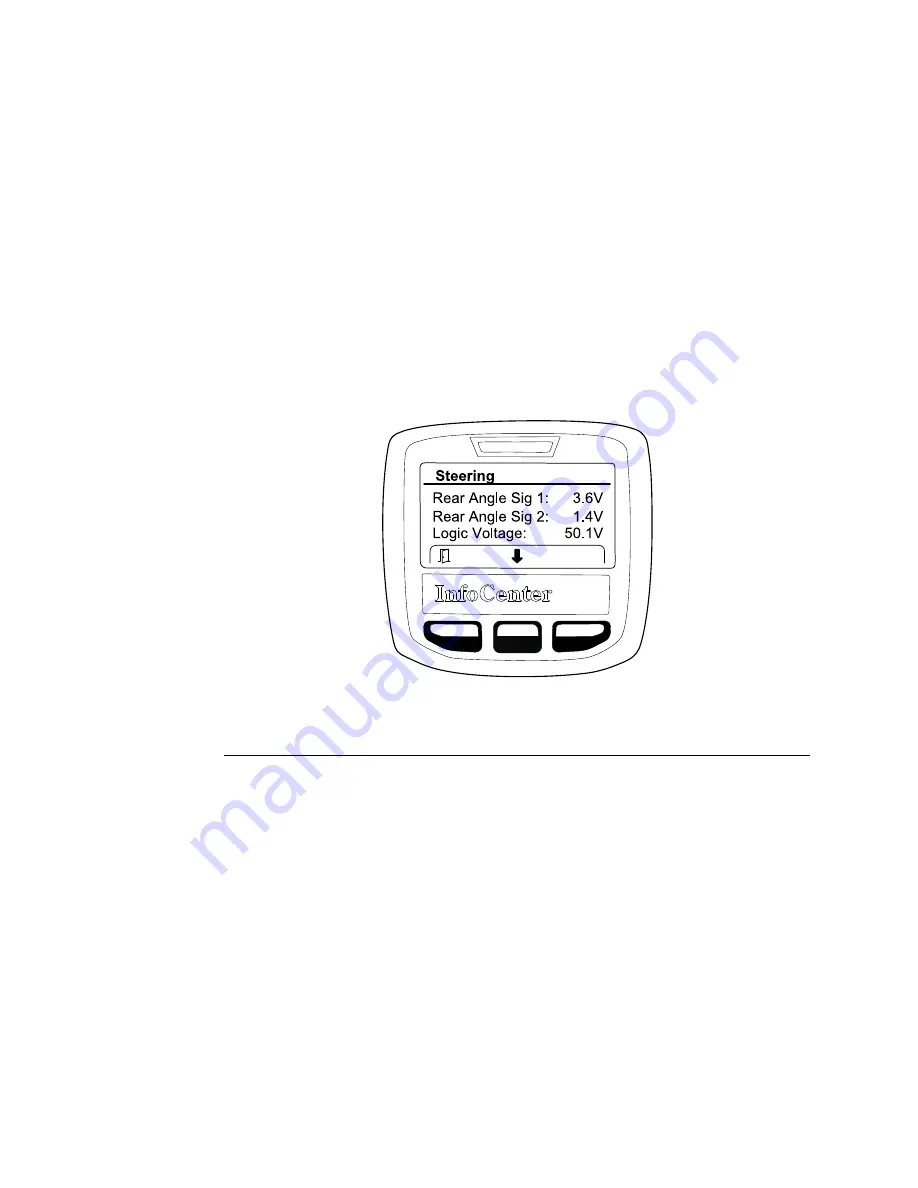
5.
Rear Angle Sig 1
and
Rear Angle Sig 2
report the amount of signal voltage
being received from the position sensor at the steering motor. Use the
InfoCenter to view the sensor signal voltage:
A. Sit in the operator seat and set the key switch to the O
N
position.
B. Set the function control switch to the N
EUTRAL
position.
C. From the InfoCenter Main Menu, select
Diagnostics > Steering > Inputs
.
g290697
Figure 82
(shown with caster fork turned to the left)
D. Turn the caster fork by hand until it is square with the machine (straight).
Rear Angle Sig 1
and
Rear Angle Sig 2
should be 2.0 – 3.0 V.
E. Turn the rear caster fork by hand fully to the left (counterclockwise).
Rear Angle Sig 1
should be 3.5 – 4.0 V and
Rear Angle Sig 2
should
be 1.0 – 1.5 V.
F. Turn the rear caster fork by hand fully to the right (clockwise).
Rear Angle
Sig 1
should be 1.0 – 1.5 V and
Rear Angle Sig 2
should be 3.5 – 4.0 V.
G. Set the key switch to the O
FF
position.
6. If any of the sensor readings are out of range, test the steering position
sensor:
A. Disconnect the machine wire harness from the steering position sensor.
Check the sensor and the harness connector for damage or corrosion
and clean or repair as necessary.
B. Connect sensor connector pins 2 and 5 to a 5 VDC power supply, and
connect pins 1 and 4 to ground.
Electrical System: Testing the Electrical Components
Page 5–90
Greensmaster® eTriFlex 3360 and 3370
19239SL Rev B


