


96
FUNCTION CHARACTERISTICS
—
Undervoltage - 27
Preface
Two operation thresholds, independently adjustable with adjustable delay.
The first one may be programmed with definite or inverse time, while the second threshold operates
with definite time characteristic.
Each threshold may be separately enabled or disabled.
The first threshold trip may be inhibited by start of the second threshold.
Operation and settings
The fundamental frequency of a selectable voltages, phase to ground (
U
L1
,
U
L2
,
U
L3
) or phase-to-pha-
se voltages (
U
12
,
U
23
,
U
31
) are utilized:
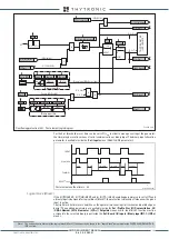
Each of three voltages compared with the setting values. The start and trip logic may be selected
OR
or
AND
.
With
OR
selection, a start is issued when at least one of the three voltages goes down the adjustable
threshold (START); with
AND
selection, a start is issued when all the three voltages go down the
adjustable threshold.
After expiry of the associated operate time a trip command is issued; if instead the voltages exceed
the threshold, the element is restored.
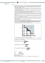
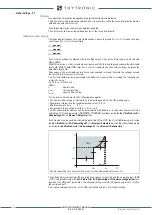
The first threshold may be programmed with definite or inverse time according the following cha-
racteristic curve:
t
=0.75
t
U<inv
/ [1-(
U
/
U
<
inv
)]
Where:
t
:
operate time
U
<
inv
:
threshold setting
t
U<inv
:
operate time setting
For the inverse time characteristic, following data applies:
• The operate time setting is referred to an input voltage equal to 1/4 of the pickup value.
• Asymptotic reference value (minimum pickup value): 0.9
U
<
• Minimum operate time: 0.1
s
• Range where the equation is valid: 0 ≤
U
/
U
<
inv
≤ 0.9
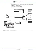
The first undervoltage element can be programmed with definite or inverse time characteristic by
setting the
U<Curve
parameter (
DEFINITE, INVERSE
) available inside the
Set \ Profile A (or B) \
Undervoltage-27 \
U
< Element \ Setpoints
menu.
Each element can be enabled or disabled by setting
ON
or
OFF
the
U< Enable
parameter inside
the
Set \ Profile A (or B) \ Undervoltage-27 \
U
< Element \ Setpoints
menu and/or the
State
parame-
ter inside the
Set\Profile A (or B) \ Undervoltage-27 \
U
<< Element \ Definite time
.
The voltage measurement type (Phase-to-phase or phase-to-neutral) and the operating logic (AND
or OR), is adjustable inside the
Set \ Profile A (or B) \ Undervoltage-27 \ Common configuration
menu
by means the
Utype27
parameter
;
the allowed setting are
Uph-ph
(phase-to-phase) or
Uph-n
(phase-to-neutral).
The corresponding unit are p.u.
U
n
for
Uph-ph
setting and p.u.
E
n
for
Uph-n
setting.
U
12
=|
U
L1
-
U
L2
|
U
23
=|
U
L2
-
U
L3
|
U
31
=|
U
L2
-
U
L1
|
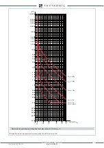
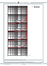
General operation time characteristic curve for the undervoltage elements - 27
U
U
<<
U
<
0.9
U
<
t
U
<<
t
t
U
<
TRIP
XMR-D EQUIPMENT MANUAL
Ed. 2.9 - 02/2021


