
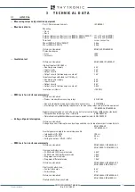


TECHNICAL DATA
29
—
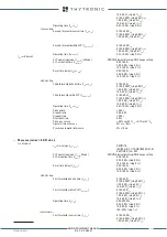
Negative sequence / positive sequence current ratio - I
2
/I
1
I
21
> Element
CLP operating mode (
I
21CLP>
Mode)
OFF/ON-Element blocking/ON-Change setting
CLP activation time (
t
21CLP>
) 0.00...100.0 s
0.00...9.99 s (step 0.01 s)
10.0...100.0 s (step 0.1 s)
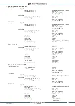
Definite time
First threshold definite time (
I
21
>
def
)
0.10...1.00
I
n
(step 0.01
I
n
)
I
2
/
I
1
> within CLP ((
I
21CLP
>
def
0.10...1.00
I
n
(step 0.01
I
n
)
Operating time (
t
21
>
def
)
0.04...15000
s
0.04...9.99 s (step 0.01 s)
1...15000 s (step 1 s)
Pickup time
≤
0.04 s
Dropout
ratio
0.95...0.98
Dropout time
≤
0.05 s
Overshoot time
0.04 s
Pickup accuracy
± 1% with
I
2
and
I
1
≥ 0.5
I
n
Operate time accuracy
5% ± 10 ms
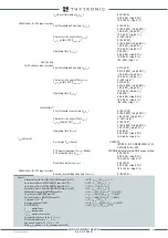
—
Phase rotation direction check - 47
47 Element
Definite time
Us
1
< Threshold (
U
s1
<
)
0.05...0.30
E
n
Us> Threshold (
U
s
>
)
0.70...1.00
U
n
Pickup time
≤
0.04 s
Dropout
ratio
0.95...0.98
Dropout time
≤
0.05 s
Overshoot time
0.04 s
Pickup
accuracy ±
0.5% on current measures
±
0.5% on voltage measures
Operate time accuracy
5% ± 10 ms
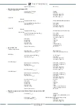
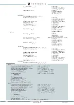
—
Thermal image for Line/Transformer protection - 49LT
Common configuration:
Initial thermal image
Dq
IN
(
Dth
IN
) 0.0...1.0
Dq
B
(step 0.1
Dq
B
)
19
Reduction factor at inrush (
K
INR
)
1.0...3.0 (step 0.1)
Thermal time constant
t
(
T
)
1...200 min (step 1 min)
CLP operating mode (
Dth
CLP
Mode)
OFF/ON-Element blocking/ON-Change setting
CLP activation time
(
t
DthCLP
)
0.00...100.0 s
0.00...9.99 s (step 0.01 s)
10.0...100.0 s (step 0.1 s)
DthAL1 Element
First alarm threshold
(
Dth
AL1
)
0.3...1.0
Dq
B
(step 0.1
Dq
B
)
DthAL2 Element
Second alarm threshold
(
Dth
AL2
) 0.5...1.2
Dq
B
(step 0.1
Dq
B
)
Dth> Element
Trip threshold (
Dth
>)
1.100...1.300
Dq
B
(step 0.001
Dq
B
)
Dropout
ratio
0.95...0.98
Dropout time
≤
0.05 s
Overshoot time
0.04 s
Pickup
accuracy ±
0.5% with 0.1
I
n
±
0.2% with 1
I
n
Operate time accuracy
5% ± 10 ms
—
Thermal image for Motor/generator protection - 49MG
Common configuration:
Initial thermal image (
Dth
IN
)
0.0...1.0
Dq
B
(step 0.1
Dq
B
)
19
20
Starting overload coefficient (
K
ST
)
1.0...3.0 (step 0.1)
Negative sequence current heating coefficient (
K
2
)
0...10 (step 1)
Heating time constant
t+
(
T+
)
1...200 min (step 1 min)
Cooling time constant
t-
(
T-
)
1.0...6.0
t
+ (step 0.1
t
+)
CLP operating mode (
Dth
CLP Mode
) OFF/Blocking/Change setting
CLP activation time (
t
DthCLP
)
0.00...200 s
0.00...9.99 s (step 0.01 s)
10.0...99.9 s (step 0.1 s)
100...200 s (step 1 s)
DthAL1 Element
First alarm threshold
(
Dth
AL1
)
0.3...1.0
Dq
B
(step 0.1
Dq
B
)
DthAL2 Element
Second alarm threshold
(
Dth
AL2
) 0.5...1.2
Dq
B
(step 0.1
Dq
B
)
Dth> Element
Note 19
Dq
is the thermal image (p.u. of the basic over temperature corresponding to the basic current
I
B
).
Assuming that the secondary rated current of the line CT’s equals the rated current of the NM20 relay, as usually happens, the IB value is the
ratio between the rated current of the protected element and the primary rated current of the CT’s
XMR-D EQUIPMENT MANUAL
Ed. 2.9 - 02/2021


