


88
FUNCTION CHARACTERISTICS
Operation and settings
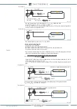
All elements can be enabled or disabled by setting
ON
or
OFF
the
Enable
and
State
parameters
inside the
Set \ Profile A (or B) \
Overexcitation - 24 \ (U/f)AL Element ((U/f)> Element or (U/f)>> Ele-
ment ) \ Setpoints(Definite time-Inverse time)
menus.
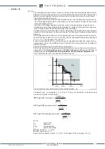
Tripping of alarm (
U
/
f
)AL and/or first element (
U
/
f
)> may be inhibited by the start of the second
element (
U
/
f
)>> by setting
ON
the (
U/f)AL disabling by
(
U/f)>>
and/or e (
U/f)> disabling by
(
U/f)>>
parameter available inside the
Set \ Profile A (or B) \
Overexcitation - 24 \ (U/f)>> Element \
Setpoints
menu.
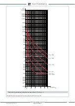
The elements are enabled in the 20 Hz ... 60 frequency range.
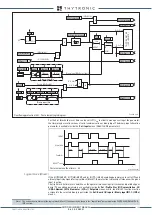
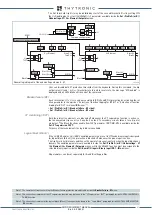
all-F24.ai
General logic diagram of the overfluxing elements - 24
U/f
U/f
U/f
Block1
Block1
Block3
Block1
Block1
Block3
Reset t
U/f>RES
Block1
Block1
U/f >> element
U/f > element
U/f
AL
element
U
/f>>
U/f>
inverse/definite-time
t
U/f>>
U/f
AL
t
U/fAL
t
U/f>
t
U/f>RES
2nd Pickup Element
1st Pickup Element
Alarm Pickup Element
U/f>> Start
U/f>> Start
U/f>> Start
U/f>> Trip
U/f> Start
U/f> Start
U/f> Trip
U/f
AL
Start
U/f
AL
Trip
U/f> inhibition
&
&
≥
U/f
AL
Inhibition
&
U/f
AL
Inhibition
U/f
AL
Inhibition
U/f> inhibition
Fun-F24_S1.ai
U/f
>
(
U/f
)
AL
&
RESET
t
U/fAL
0
T
TR
IP
PIN
G
M
AT
RIX
(
LE
D+R
EL
AY
S)
U/f
AL
t
U/fAL
U/f AL Start
U/f AL Start
U/f AL Trip
U/f AL Trip
≥
1
(ON
≡
Inhibit)
(ON
≡
Inhibit)
F24SA Block3
IF Start
U/f> Block1
U/f
U/fAL Inhibition
U/f> Inhibition
=0 if 20≤f≤60 Hz
U/f AL Start
U/f AL Trip
&
&
&
Enable (ON
≡
Enable)
Block1 input (ON
≡
Block)
Block1
Block1
Block1
Binary input INx
T
0
Logic
INx
t
ON
INx
t
ON
INx
t
OFF
T
0
n.o.
n.c.
INx
t
OFF
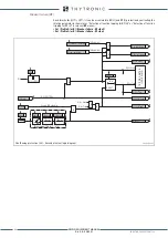
Overfluxing protection (24) - Alarm element logic diagram
XMR-D EQUIPMENT MANUAL
Ed. 2.9 - 02/2021


