


FUNCTION CHARACTERISTICS
255
Fun_67S3.ai
I
L1
I
L1
∙cos
≥
1
≥
1
ON
≡
Inhibit (fromIPD>>>> element)
ON
≡
Enable IPD>>> directional overcurrent element
IPD>>> inhibition
&
&
&
&
&
I
PDCLP>>def
≥
I
PDCLP
>>>
A
B
C =“2/3”
C
Non-directional
(from 74VT)
Non-directional
D =“1/3”
A = Directional B = Non-directional
Logic67
C
D
IPD>>> Enable
≥
1
CB-State
Start
I
2ndh>
Block1, Block2, Block4
T
0
t
CLP>
&
2nd harmonic restraint enable (ON
≡
Enable)
I>2ndh-REST
IPDCLP>>>Mode
t
PDCLP>>>
A
B
C
A =“1”
A =“0 or OFF”
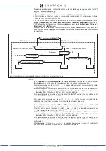
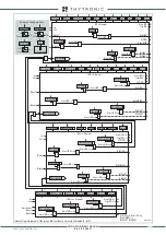
IPD> overcurrent directional element (67) block diagram
A = ON - Change setting within CLP
B = OFF - CLP disabled
C = ON - Element blocking within CLP
≥
1 CLP IPD>>>
IPD> inhibition
&
State
≥
I
PD>>>def
I
PD>>>def
Settore
ThetaP
>>>
Settore
Settore
Mode67
I
L2
I
L2
∙cos
I
L3
I
L3
∙cos
I
L1
I
L2
I
L3
I
PDCLP>>>def
≥
I
PDCLP
>>>def
&
State
≥
I
PD>>>def
I
PD>>>def
≥
1
Block by 74VT
(ON
≡
Block)
Internal or external
OFF
74VT
74VTint/ext67
t
PD>>RES
T
0
RESET
t
PD>>>def
0
T
t
PD>>>RES
IPD>disby IPD>>>
Start IPD>>>
Trip IPD>>>
TR
IP
PI
NG M
AT
RI
X
(LE
D+R
EL
AY
S)
IPD>>>TR-K
IPD>>>TR-L
IPD>>>ST-L
IPD>>>ST-K
t
PD>>>def
D
A
B
&
IPD>> inhibition
IPD>>disby IPD>>>
Start IPD>>>
Start IPD>>>
Input U
31
Input U
23
Input U
12
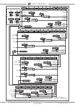
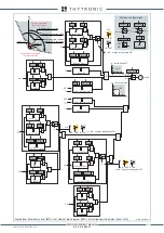
Phase directional overcurrent (67) - Third element logic diagram (IPD>>>)
XMR-D EQUIPMENT MANUAL
Ed. 2.9 - 02/2021


