


FUNCTION CHARACTERISTICS
285
Module
If the
module
principle and the operation mode is not switched to “not directional” (by the 74VT fun-
ction), the start of any 67N(Comp) threshold becomes active when the following A) and B) conditions
are contemporaneously active:
A) in the “Insens-Zone=OFF” operating mode:
- The residual current (
I
ECH
or
I
ECL
) fundamental component overcomes the threshold (
I
EDC>
,
I
EDC>>
,
I
EDC>>>
,
I
EDC>>>>
)
AND
- The residual voltage (
U
E
or
U
EC
) fundamental component overcomes the threshold (
U
ED>
,
U
ED>>
,
U
ED>>>
,
U
ED>>>>
),
while in the “Insens-Zone=ON” operating mode:
- The residual current (
I
ECH
or
I
ECL
) fundamental component overcomes the threshold (
I
ED>
,
I
ED>>
,
I
ED>>>
,
I
ED>>>>
)
AND
- The residual current (
I
ECH
or
I
ECL
) fundamental component overcomes the threshold (M∙
U
ED>
,
M∙
U
ED>>
,
M∙
U
ED>>>
, M∙
U
ED>>>>
)
OR
- The residual current (
I
ECH
or
I
ECL
) fundamental component overcomes the threshold (M∙
I
ED>
,
M∙
I
ED>>
,
M∙
I
ED>>>
, M∙
I
ED>>>>
)
AND
The residual voltage (
U
E
or
U
EC
) fundamental component overcomes the threshold (
U
ED>
,
U
ED>>
,
U
ED>>>
,
U
ED>>>>
).
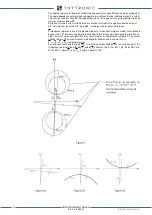
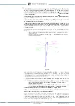
B) The residual current phasor (
I
ECH
or
I
ECL
) is located inside the angular sector defined by own cha-
racteristic angle (
β
E
>,
β
E
>>,
β
E
>>>,
β
E
>>>>) and half operating sector (
Θ
E
>,
Θ
E
>>,
Θ
E
>>>,
Θ
E
>>>>),
that is the -
β
E
≤ (
Θ
E
-
Φ
E
) ≤ +
β
E
condition is fulfilled.
If the operation mode is switched to “not directional” (by the 74VT function), the start of any 67N
threshold becomes active when the following is complied:
- The residual current (
I
ECH
or
I
ECL
) fundamental component overcomes the threshold (
I
EDC>
,
I
EDC>>
,
I
EDC>>>
,
I
EDC>>>>
)
The operating mode (
Mode67NComp
), the residual voltage measurement type (
Type67NC
), the
insensibility zone enabling (I
nsens-Zone(C)
), the threshold multiplier for the insensibility zone
(
M(C)
) and the operation from 74VT (
74VText67NC
) may be selected by setting the concerning
parameters, located inside the
Set\Profile A (or B)\Directional earth fault overcurrent-67N \
Common
configuration
menu.
The settable operating mode is
I
(module) or
I*cos
(projection).
Projection
If the
projection
principle and he operation mode is not switched to “not directional” (by the 74VT
function), the start of any 67N threshold becomes active when the following C) condition is active:
C) in the “Insens-Zone=OFF” operating mode:
- Residual current projection on the characteristic axis (
I
ECH
or
I
ECL
)∙cos(
Φ
E
-
Θ
E
) > 0
AND
- The residual current projection on the characteristic axis (
I
ECH
or
I
ECL
)∙cos(
Φ
E
-
Θ
E
) overcomes the
threshold (
I
ED>
,
I
ED>>
,
I
ED>>>
,
I
ED>>>>
)
AND
- The residual voltage (
U
E
or
U
EC
) fundamental component overcomes the threshold (
U
ED>
,
U
ED>>
,
U
ED>>>
,
U
ED>>>>
).
AND
The residual current phasor (
I
ECH
or
I
ECL
) is located inside the angular sector defined by own cha-
racteristic angle (
β
E
>,
β
E
>>,
β
E
>>>,
β
E
>>>>) and half operating sector (
Θ
E
>,
Θ
E
>>,
Θ
E
>>>,
Θ
E
>>>>),
that is the -
β
E
≤ (
Θ
E
-
Φ
E
) ≤ +
β
E
condition is fulfilled.
[1]
While in the “Insens-Zone=ON” operating mode:
- Residual current projection on the characteristic axis
I
E2
∙cos(
Φ
E
-
Θ
E
) > 0
AND
- The residual current projection on the characteristic axis (
I
ECH
or
I
ECL
)∙cos(
Φ
E
-
Θ
E
) overcomes the
threshold (
I
EDC>
,
I
ED>>
,
I
EDC>>>
,
I
EDC>>>>
)
AND
- The residual voltage (
U
E
or
U
EC
) fundamental component overcomes the threshold (M∙
U
ED>
,
M∙
U
ED>>
,
M∙
U
ED>>>
, M∙
U
ED>>>>
)
OR
The residual current projection on the characteristic axis (
I
ECH
or
I
ECL
)∙cos(
Φ
E
-
Θ
E
) overcomes the
threshold (M∙
I
EDC>
, M∙
I
EDC>>
,
M∙
I
EDC>>>
, M∙
I
EDC>>>>
)
AND
- The residual voltage (
U
E
or
U
EC
) fundamental component overcomes the threshold (
U
ED>
,
U
ED>>
,
U
ED>>>
,
U
ED>>>>
).
AND
The residual current phasor (
I
ECH
or
I
ECL
) is located inside the angular sector defined by own cha-
racteristic angle (
β
E
>,
β
E
>>,
β
E
>>>,
β
E
>>>>) and half operating sector (
Θ
E
>,
Θ
E
>>,
Θ
E
>>>,
Θ
E
>>>>),
Note 1 For each threshold the projection of the residual current phasor on the characteristic axis is:
(
I
ECH
or
I
ECL
)
cos(
Θ
E
>-
Φ
E
), I
(
I
ECH
or
I
ECL
)
cos(
Θ
E
>>-
Φ
E
),
(
I
ECH
or
I
ECL
)
cos(
Θ
E
>>>-
Φ
E
),
(
I
ECH
or
I
ECL
)
cos(
Θ
E
>>>>-
Φ
E
) when “direct” residual voltage is selected (U
E
), or
I
ECH
or
I
ECL
)
cos(
Θ
E
>-
Φ
EC
),
(
I
ECH
or
I
ECL
)
cos(
Θ
E
>>-
Φ
EC
),
(
I
ECH
or
I
ECL
)
cos(
Θ
E
>>>-
Φ
EC
),
(
I
ECH
or
I
ECL
)
cos(
Θ
E
>>>>-
Φ
EC
) when “calculated”
residual voltage is selected (U
EC
).
The
Θ
E
,
β
E
and
Φ
EC
symbols are not used inside the Thyvisor and MMI menus.
XMR-D EQUIPMENT MANUAL
Ed. 2.9 - 02/2021


