


172
FUNCTION CHARACTERISTICS
—
Negative sequence current / positive sequence current ratio - I2/I1
Application
The main purpose of the function is to detect the broken conductors (series faults) without earth
faults or with earth fault on soil with low resistivity; interruption of secondary currents circuits (se-
condary CTs or link) are also detect.
Operation and settings
The broken conductor condition is detected by the rise of the asymmetry between the three-phase
currents and then by the presence a negative sequence current I2 comparatively to the positive
sequence current I1.
The measure of I2 relative to I1 allows to detect the fault even in condition of lightly load where the
negative sequence current, due to the broken of the conductor, could be of the same order of magni-
tude as that present in maximum load conditions due to CTs errors (the I2 /I1 ratio still approximately
constant when the load current varies).
Two operation principles can be applied based on zero and on negative sequence currents; the first
is valid for detecting faults with ground contact of soils with low resistivity, while the latter is valid for
detecting faults without ground contact or with contact on high resistivity soils.1
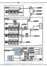
The sequence network connection diagram for an open circuit fault is detailed in the following fi-
gure where we see that when a conductor open circuit occurs, current from the positive sequence
network will be series injected into the negative and zero sequence networks across the break.
It follows that, for an open circuit, the I2 /I1 ratio can be determined from the ratio of zero sequence
to negative sequence impedance.
Because this ratio may vary depending upon the fault location, a maximum sensitive setting must be
applied; in practice, this minimum setting results from the standing negative phase sequence current
of the system.
For considering the maximum possible value, the negative sequence current must be measured at
maximum load conditions.
The threshold setting may be based upon the maximum value of I2 /I1 ratio that can be detected by
means of the measures available in the same device (
Read \ Measures \ Sequence
menu).
With sensitive settings, to avoid nuisance tripping for any unbalance condition, a long operating time
must be set to ensure co-ordination with other protective devices.
The negative and positive sequence currents are computed as:
I
1
=(
I
L1
+e+
j120°
·
I
L2
+e
-j120°
·
I
L3
)/3
I
2
=(
I
L1
+e-
j120°
·
I
L2
+e
+j120°
·
I
L3
)/3
where e
-j120°
=-1/2-j√3/2, e
j120°
=-1/2+j√3/2.
The negative sequence-positive sequence currents ratio is compared with the setting value. Ratio
above the associated pickup value is detected and a start is issued. After expiry of the associated
operate time (
t
21
>) a trip command is issued; if instead the I2/I1 ratio drops below the threshold, the
element is restored.
Z
1
=
Z
1X
+
Z
1Y
(Positive sequence impedance)
Z
2
=
Z
2 X
+
Z
2Y
(Negative sequence impedance)
Z
0
=
Z
0X
+
Z
0Y
(Zero sequence impedance)
I
1
=
E·
(
Z
2
+
Z
0
)
Z
1
Z
2
+
Z
1
Z
0
+
Z
2
Z
0
I
2
I
1
Z
0
Z
2
+
Z
0
I
2
=-
E·Z
0
Z
1
Z
2
+
Z
1
Z
0
+
Z
2
Z
0
=
Sequence connection diagram - I2/I1
Y
X
L1
L2
L3
N
Z
1X
I
1
E
I
1
Z
1Y
X1
Y1
Z
2 X
I
2
I
2
Z
2Y
X2
Z
0X
I
0
I
0
Z
0Y
X0
N
0
N
2
N
1
Y0
XMR-D EQUIPMENT MANUAL
Ed. 2.9 - 02/2021


