


52
FUNCTION CHARACTERISTICS
Analogue processing
The following are envisaged:
• Anti aliasing filter circuits
• Amplifier circuits for conditioning the input signals
• Reference voltage adjustment circuits for the measurement A/D converter
XMR relays use a DSP processor operating at 166 MHz; it performs all the processing on the analo-
gue signals and furthermore coordinates management of the TX-RX signals to the CPU.
The measurement criterion allows precise measurement of even those signals having a unidirectio-
nal component, such as transient currents with overlapping exponential, which typically appear du-
ring faults.
CPU
A 32 bit CPU is provided.
The following are envisaged:
• Real Time Clock circuits with oscillator and super capacitor
• RS232 communication port
• RS485 communication port
• Network communication circuits (optional Ethernet)
Memories:
• SRam: high speed static memory, used for data and cache
• Flash memory: used for fw storage and upgrade
• EEprom memory: used for calibration data storage
• FPGA for data transfer between CPU and DSP
—
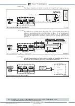
Input board
Inductive CT and VT inputs version:
• Three CTs committed for phase currents acquisition
• One CT committed for residual current acquisition
The input circuits are suitable for 1 A or 5 A external CTs
[1]
• Three VTs committed for phase voltages acquisition
• One VT committed for residual voltage acquisition
or:
• Six voltage inputs for the measurement of the three currents and three phase voltages
• One CT committed for residual current acquisition
—
MMI (Display, Keyboard and LED)
The MMI module (Man Machine Interface) includes:
• Graphic backlight LCD display with 9-keys touchscreen keyboard
• Membrane keyboard with 10 keys
• Twenty one signaling LED
• Ethernet port for local interface
Note 1 The phase and residual nominal currents must be adjusted by means dip-switch.
XMR-D EQUIPMENT MANUAL
Ed. 2.9 - 02/2021


