


FUNCTION CHARACTERISTICS
103
One adjustable operation threshold, (
U
E3H
<) with definite time adjustable delay (
t
UE3H
<).
In order to avoid unwanted operation of protection to stop the generator or operating conditions
at low load conditions, where the third harmonic component is absent, the following controls are
provided:
• Generator stopped: the inhibition of protection can be obtained by activating a logic input. The set-
tings are available inside
100% stator earth-fault with 3rd harmonic - 27H-59H \ 1st Pickup Element
\ Setpoint
menu; if the
Block1
enabling parameters are set to
ON
and a binary input is designed for
logical block (Block1), the protection is blocked off whenever the given input is active.
The trip timer is held in reset condition, so the operate time counting starts when the input block
goes down.
[1]
The enabling parameters are available inside the
Profile A(or B) \ Undervoltage-27
\ 1st Pickup Element (2nd Pickup Element) \ Setpoints
menus, while the
Block1
function must be
assigned to the selected binary input inside the
Common parameters \
Binary input allocation
menu.
menus (IN1 or INx matching). In particular it is cleared the trop timer, so the operating time count
begins when the signal block goes OFF. Alternatively, inhibition can be obtained by programming an
undervoltage control. The 100% stator earth would then be inhibited when all three voltages measu-
red by the VTs fall below an adjustable threshold (
U
IN-3H
<)). This requires the setting to ON of the the
State
parameter
of the
U
IN-3H
< threshold.
• Generator at low load: inhibition of the protection can also be set when all three phase currents
are below an adjustable threshold (
I
IN-3H
< ) in order to avoid the trip with generators with no third
harmonic voltage at reduced load. This requires the Status parameter set to ON on the
I
IN-3H
<thre-
shold. This inhibition is off the intervention of the monitoring function of the CT. This requires the
setting to ON of the the
State
parameter
of the
U
IN-3H
< threshold. This inhibition is cleared when
the CT Supervision function (74CT) becomes active.
Measurement of residual voltage measured by VT secondary open delta on the generator line
The operating logic must be programmed as third harmonic overvoltage protection (59H) in order to
detect an increase in the value of third harmonic component of residual voltage (present in normal
operation), in the case of earth fault near the star center.
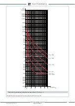
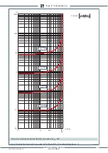
The development of the third harmonic residual voltage on the winding stator is shown in the fol-
lowing figure.
Note 1 The exhaustive treatment of the logical block (Block 1) function may be found in the “Logic Block” paragraph inside
CONTROL AND MONITOR-
ING
section.
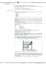
U
U
E3H
<
t
t
UE3H
<
TRIP
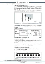
General operation time characteristic curve for the third harmonic undervoltage element - 27H
U
E3H
<
U
IN-3H
<
I
IN-3H
<
U
E3H
>
t
UE3H
<
t
UE3H
>
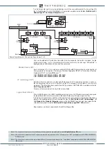
UE3H mode
UE3H element
U< inhibition
U< inhibition
Block1
Block1
Block3
UE3H Start
UE3H Trip
U
E 3H
AND
27H-59H Element
Inhibit
U
<
U
12
,
U
2 3
,
U
31
U <
U
IN-3H
<
AND
Inhibit
I
<
I
L1
,
I
L 2
,
I
L 3
I <
I
IN-3H
<
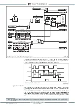
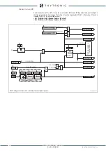
General logic diagram of the 3rd harmonic undervoltage/overvoltage element - 27H-59H
XMR-D EQUIPMENT MANUAL
Ed. 2.9 - 02/2021


