


FUNCTION CHARACTERISTICS
95
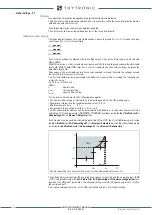
All alarm and/or trip elements can be enabled or disabled by setting
ON
or
OFF
the
ThALx Enable
e
Th>x Enable
parameters inside the
Set \ Profile A (or B)\ Thermal protection with RTD thermo-
metric probes - 26 \
PTx Probe \ ThALx Alarm (ThALx Trip)
where x = 1...8
.
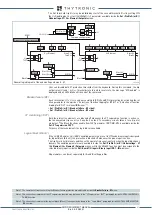
Breaker failure (BF)
Th>x threshold can be associated to BF (H) and BF (L) protection by activating the relative parameter
in the matrices “Selection of function tripping for BF (H)” or “Selection of function tripping for BF (L)”
in relevant
BF
menus
[1]
:
• Set \ Profile A (or B) \ Breaker failure - BF side H
• Set \ Profile A (or B) \ Breaker failure - BF side L
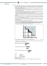
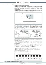
In order to compensate the additional resistance introduced by the cables, three wires connection is
recommended (example 1); with only two terminals, probes you must use a shielded cable with three
conductors carrying the schematic example 2 (Pt100 connected to T2 in the figure).
However it is essential that the link between Terminal A and Terminal B is made with cables of the
same type (same link resistance).
For very short connections, two wires (Pt100 connected to T8 example 3) are permitted; the non-com-
pensated resistance connections resulting in an error proportional to the value of introduced resi-
stance.
The connection to the probes must be made with three conductors shielded cables and the screen
should be earthed only at one end, preferably on the relay; multiple connections may result in current
circulation on the screen resulting noise on the measure and are therefore to avoid.
It is recommended to position connections to the probe away from power lines to avoid interference.
Note 1 The common settings concerning the Breaker failure protection are adjustable inside the
Breaker Failure - BF
menu.
Example 1
Example 2
Example 3
XMR-x
Pt100 BOARD
PT1
MPT1
GND1
PT2
MPT2
PT8
MPT8
T1
A
B
Pt100
T2
T3...T7
T8
A
B
Pt100
Pt100
Fun-F26.ai
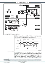
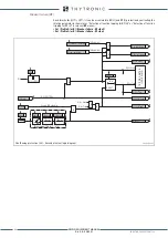
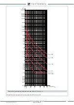
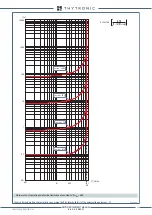
Logic diagram for thermal protection with RTD thermometric probes (26)
T°
≤
+24 5.0°C
T°
>
Pt
x
>
Pt
x
Pt1
Pt2
Pt3
Pt4
Pt5
Pt6
Pt7
Pt8
0
T
TR
IP
PI
NG M
AT
RI
X
(LE
D+R
EL
AY
S)
T°
>
Th
ALx
Pt100-
x Trip
Pt100-
xAlarm
t
Th
>
x
t
ThALx
Pt100 OK
Pt100 FAULT
TOWARDS DIAGNOSTIC
Pt
x
> Diagnostic
&
&
T°
≥
-4 9.0°C
0
T
ThALx-K
ThALx-L
Th>x-K
Th>x-L
Th
ALx
Th
>
x
t
ThALx
t
Th
>
x
XMR-D EQUIPMENT MANUAL
Ed. 2.9 - 02/2021


