


FUNCTION CHARACTERISTICS
227
—
Residual overvoltage - 59N
Preface
Two operation thresholds, independently adjustable with adjustable delay.
The first one (
U
E
>) may be programmed with definite or inverse time, while the second threshold
operates with definite time characteristic.
Each threshold may be separately enabled or disabled.
The first threshold trip may be inhibited by start of the second threshold.
Operation and settings
Two measuring criteria of the residual voltage are provided:
• Direct
• Calculated.
For direct measure the fundamental component of the residual voltage input is used (
U
E
), whereas,
for calculated measure (
U
EC
) the residual voltage comes from a vector sum of three phase voltage
phasors.
The residual voltage (
U
E
or
U
EC
) is compared with the setting values (
U
E
>,
U
E
>>); a start is issued
when the residual voltage overcomes the adjustable threshold (START); after expiry of the asso-
ciated operate time (
t
UE
>,
t
UE
>>) a trip command is issued; if instead the voltage drops below the
threshold, the element is restored.
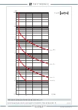
The first threshold (
U
E
>) may be programmed with definite or inverse time according the following
characteristic curve:
t
=0.5
t
UE
> / [(
U
E
/
U
E
>
inv
) - 1] (direct meaure of
U
E
for VTs input versions) or
t
=0.5
t
UE
> / [(
U
EC
/
U
E
>
inv
) - 1] (calculated measure of
U
EC
for VTs input versions or ThySensor)
where:
U
E
:
measured residual voltage
U
EC
:
calculated residual voltage
t
:
operate time
U
E
>
inv
:
threshold setting
t
UE>inv
:
operate time setting
For the inverse time characteristic, following data applies:
• The operate time setting is referred to an input voltage equal to 1.5 of the pickup value.
• Asymptotic reference value (minimum pickup value): 1.1
U
E
>
inv
• Minimum operate time: 0.1
s
• Range where the equation is valid: 1.1 ≤
U
E
/
U
E
>
inv
≤ 4
• If
U
E
>
inv
pickup ≥ 0.5
U
En
, the upper limit is 2
U
En
.
The first residual overvoltage element can be programmed with definite or inverse time characteri-
stic by setting the
UE> Curve
parameter (
DEFINITE, INVERSE
) available inside the
Set \ Profile
A (or B) \ Residual overvoltage-59N \
UE
> Element \ Setpoints
menu.
Each element can be enabled or disabled by setting
ON
or
OFF
the
UE> Enable
parameter inside
the
Set \ Profile A (or B) \ Residual overvoltage-59N \
UE
> Element \ Setpoints
menu and/or the
State
parameter inside the
Set \ Profile A (or B) \ Residual overvoltage-59N \ UE>> Element \ Definite time
.
Selection of the measuring criteria of the residual voltage (direct measure or calculated measure) is
available inside the
Set \ Profile A (or B) \ Residual overvoltage-59N \
Common
configuration
menu;
The
3Votype59N
parameter may be select as
UE
(direct measure) or
UEC
(calculated measure).
U
EC
=|
U
L1
+
U
L2
+
U
L3
|
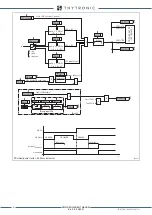
t-int-F59N.ai
U
E
U
E
>>
t
UE
>
t
UE
>>
U
E
>
t
TRIP
General operation time characteristic for the residual overvoltage elements - 59N
XMR-D EQUIPMENT MANUAL
Ed. 2.9 - 02/2021


