


366
INSTALLATION
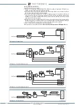
Amperometric inputs
The amperometric input circuits are mounted on the input module (terminals A1...10 for L side and
Z1...10 for H side).
In case of replacement of the relay or checks on the amperometric circuits is essential to provide
appropriate support to achieve the secondary circuit shorting. For security reasons it is advisable to
operate in the absence of line current.
When making the current connections, attention must be paid to not exceeding the performance of
the line current transformers. To be exact, the total load, the protective relay, any other protective
relays or measuring instruments and the resistance of the connections, must not exceed the line CT
performance.
In particular, consumption of the relay input circuit must not exceed 0.3 VA while the load (expressed
in VA) constituted by the conductors is given by:
0.018 × L ×
I
n
2
/ S
where:
L the overall length, expressed in m, of the two conductors in relation to each phase;
I
n
nominal current of the line CT expressed in A;
S cross sectional area of the current conductors expressed in mm
2
.
It is recommended that cabling of a suitable thickness be used in order to limit wear of the CT se-
condary circuits.
Earth connection
A protective ground connection is required: the section of the cable shall be not less than 2.5 mm
2
.
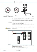
Core balanced CT
The current balance transformer, when used for measuring residual current, must be crossed in the
same direction by all active conductors and hence, also by the neutral conductor if distributed, with
the exception of the ground connection protective conductor. The drawing below shows cases of
assembly of the toroid on unscreened and screened cables; prior to proceeding with assembly, it is
necessary to check that there are no screen-to-ground connections upstream of the sensor..
In order to ensure a linear response from the sensor, the cables must be positioned in the centre
of the transformer so that the magnetic effect of the three cables is perfectly compensated in the
absence of residual current (Fig.2a).
Fig. 1a
Fig. 1b
Armoring
Load
Load
Source
Source
Insulated cables
Shielded cables
Armoring
Toroide.ai
Current balanced transformer
If the secondary of a CT carrying primary current is open circuited, a high voltage can be developed
across the CT terminals.
CAUTION
XMR-D EQUIPMENT MANUAL
Ed. 2.9 - 02/2021


