


APPENDIX
378
8.1
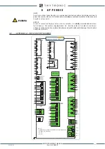
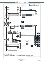
APPENDIX A1 - INPUT-OUTPUT SCHEME
8 A P P E N D I X
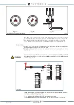
INPUT
For all connections longer than 5m or in environments particularly subject to disturbances due to
power transmission, the use of shielded cables is
strictly
recommended, with the shield connected
to earth on only one end.
OUTPUT
In case of connections to power relays coils or contactors, it is
strictly
recommended install pro-
tection devices - like varistors, trapping diodes, etc. - directly on the coils in order to avoid over-
voltage phenomena which can produce disturbances along the cables and/or damage the coils and/or
control relays contacts.
Note [1]
2 redundant ports selectable with HW-SW switch command among:
• TX (RJ45) + FX (Fibre Optic)
• TX + TX
• FX + FX
U
L1
U
L2
U
L3
U
E
VOL
TAGE INPUTS
7
8
5
6
3
4
1
2
1
I
L1
-L
I
L2
-L
I
L3
-L
I
E1
CURRENT INPUTS
2
3
4
5
6
7
8
Local Ethernet
RS485
2
3
B-
A+
X
U
AUX
1
≅
2
C
B
A
IN1F
BINARY INPUTS
1
2
3
4
5
6
7
8
9
10
IN2G
BINARY INPUTS
1
2
3
4
5
6
7
8
9
10
OUTPUT RELA
YS
E3
E4
E5
E6
E7
E8
K1
K2
E1
E2
K3
K4
K5
K6
K7
L1
L2
L3
L9
L10
OC1L
K1-1
L4
L5
L6
K1-2
L7
L8
K1-3
K1-4
XMR-D
OPTIONS
TX
[1]
TX
[1]
FX
[1]
FX
[1]
ETHERNET
1
R_TERM
D1
D2
D3
D4
D5
D6
E9
E10
M1
M2
M3
M9
M10
OC2M
K2-1
M4
M5
M6
K2-2
M7
M8
K2-3
K2-4
IN3H
BINARY INPUTS
1
2
3
4
5
6
7
8
9
10
1
I
L1
-H
I
L2
-H
I
L3
-H
I
E2
CURRENT INPUTS
2
3
4
5
6
7
8
Z
V
I
64F INPUTS
L-IN
COM-RES
PE
Y
1
2
3
X
BL
OUT
BL
IN
3
4
1
2
WARNING
XMR-D EQUIPMENT MANUAL
Ed. 2.9 - 02/2021


