


FUNCTION CHARACTERISTICS
229
Fun-F59N_S1.ai
≥
1
U
E
> Inhibition
(ON
≡
Inhibit)
Block 74VT
(ON
≡
Inhibit)
&
U
E
> Curve
0
T
RESET
t
UE>
0
T
TR
IP
PI
NG M
AT
RI
X
(LE
D+R
EL
AY
S)
t
UE>def
t
UE>inv
Start U
E
>
U
E
>ST-K
U
E
>ST-L
Start U
E
>
Trip U
E
>
U
E
>TR-K
U
E
>TR-L
Trip U
E
>
Block1 U
E
>
74VT ext.
&
&
&
Enable (ON
≡
Enable)
Block1 input (ON
≡
Block)
Block1
Block1
Block1
Binary input INx
T
0
Logic
INx
t
ON
INx
t
ON
INx
t
OFF
T
0
n.o.
n.c.
INx
t
OFF
&
Enable (ON
≡
Enable)
74VTint59N
74VText.
Binary input INx
T
0
Logic
INx
t
ON
INx
t
ON
INx
t
OFF
T
0
n.o.
n.c.
INx
t
OFF
t
UE>RES
T
0
t
UE>RES
ON
≡
Enable UE> residual overvoltage element
UE
>
Enable
U
E
U
E>def
U
E>inv
≥
1
&
State
U
E
≥
U
E>def
U
E
≥
U
E>inv
&
State
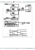
Logic diagram concerning the first threshold (UE>) of the residual overvoltage element - 59N
Fun-F59N_S2.ai
≥
1
Block 74VT
(ON
≡
Inhibit)
&
RESET
t
UE>>
0
T
TR
IP
PI
NG M
AT
RI
X
(LE
D+R
EL
AY
S)
t
UE>>def
Start U
E
>>
U
E
>>ST-K
U
E
>>ST-L
Start U
E
>>
Trip U
E
>>
U
E
>>TR-K
U
E
>>TR-L
Trip U
E
>>
Block1 U
E
>>
74VT ext.
&
&
&
Enable (ON
≡
Enable)
Block1 input (ON
≡
Block)
Block1
Block1
Block1
Binary input INx
T
0
Logic
INx
t
ON
INx
t
ON
INx
t
OFF
T
0
n.o.
n.c.
INx
t
OFF
&
Enable (ON
≡
Enable)
74VTint59N
74VText.
Binary input INx
T
0
Logic
INx
t
ON
INx
t
ON
INx
t
OFF
T
0
n.o.
n.c.
INx
t
OFF
t
UE>>RES
T
0
t
UE>>RES
U
E
U
E>>def
&
State
U
E
≥
U
E>>def
&
(ON
≡
Inhibit)
UE> Inhibition
UE>disbyUE>>
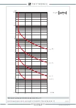
Logic diagram concerning the second threshold (UE>>) of the residual overvoltage element - 59N
XMR-D EQUIPMENT MANUAL
Ed. 2.9 - 02/2021


