14
GENERAL
—
Main features
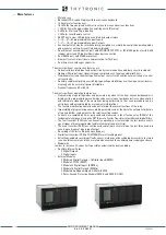
• Metallic case
• Backlight LCD Graphic Display with touchscreeen keyboard
• 10 Accelerator function keys
• 16 LEDs that may be joined with matrix criteria to many and various functions
• 1 LED for Power Supplay indication and Diagnostic (Flashing)
• 2 LEDs for Start and Trip indication
• 2 LEDs for Local/Remote control
• RESET key to clear LED indications and latched output relays
• 7—14—21—53 programmable Logical Inputs
• 7—11—15—31 programmable Logical Outputs
• Each output relay may be set with normally energized or normally de-energized operating mode
and manual or automatic reset (latched/no-latched).
• Rear Ethernet communication port, with MODBUS TCP/IP® or IEC61850 protocol, with RJ45
(copper wires) and FX (optical fiber) redundant connection.
• Rear RS485 port, with ModBus protocol.
• Ethernet front serial port (local communication for ThyVisor).
• Real time clock with super capacitor.
The most significant constructive features are:
• Galvanically insulated input and output circuits (communication and binary circuits included).
• Optimum filtering of input signals through combined use of analog and digital filters.
• Traditional electromechanical-type final output contacts with continuous monitoring of control
coil continuity.
• Auxiliary supply comprising a switching-type voltage stabilizing circuit having a very wide wor-
king range and a very small power dissipation
• Nominal frequency: 50 or 60 Hz.
The most significant operating features are:
• Programming of operating modes and parameters by means of the front keys and alphanumeric
display, with a programming procedure based on carrying out guided selections and on explicit
and immediate signalling of the operations being performed, so that such procedure can be
carried out without coding tables or mnemonic informations.
• The feature modification operations do not interrupt the normal functions of the relay.
• Impossibility of programming unacceptable parameter values, thanks to the automatic limitation
of top and bottom scale values for the relative setting ranges.
• Currents are sampled 64 times per period and measured in the effective value (RMS) of the
fundamental component using the DFT (Discrete Fourier Transform) algorithm and digital filters.
• The fault recorder (SFR) runs continuously capturing in circular mode the last twenty events
upon trigger of binary input/output and/or element pickup (start-trip).
• The event recorder (SER) runs continuously capturing in circular mode the last three hundred
events upon trigger of binary input/output.
• Recording of the last setting changes (Logger).
• Digital fault recorder (DFR) in COMTRADE format (oscillography).
• All settings and data recordings (faults, events, meterings and oscillography records) are stored
in non-volatile memory and then are retained even when the auxiliary power supply goes down.
• Modularity
In order to increase I/O capacity it’s possible customized the device adding :
• Auxiliary Internal Cards
◊ Digital Outputs
◊ Digital Inputs
• External Modules
◊ Module 8 Digital O 16 Digital Inputs(XMRI)
◊ Module 8 PT100 (XMPT)
◊ Module 32 Digital Inputs (XMID32)
◊ Module 16 Digital Outputs (XMR16)
◊ Module 6 Analogue Outputs 4÷20mA (XMCI)
◊ Rotor-Ground Protection Module (XMR-P and XMR-D ONLY)
XMR-D EQUIPMENT MANUAL
Ed. 2.9 - 02/2021


