


APPENDIX
381
(*) Antiferrorisonance
L1 L2 L3
P1
S1
S2
P2
I
L1H
I
L2H
I
L3H
A2
A1
A3
A4
A5
A6
P1
S1
S2
P2
I
L1L
I
L2L
I
L3L
BF
74TCS
74CT
74CT
74VT
66
M
46
49
50/51
50/51
51LR
37
37P
32P
40
Z7
Z8
I
E2
P1
S1
S2
P2
U
L1
U
L2
U
L3
A
N
B
N
C
N
n
a
n
b
n
c
B1
B2
B3
B4
B5
B6
B7
B8
dn
da
dn
db
dn
dc
(*)
27
55
27V1
59V2
81O
81U
59
87M
I
ECL
I
ECH
26
85NHIZ
*
U
L1
,
U
L2
,
U
L3
I
L1L
,
I
L2L
,
I
L3L
I
L1H
,
I
L2H
,
I
L3H
I
ECH
I
ECL
50N/51N(Comp)
U
EC
59N
U
E
U
E
U
EC
U
EC
67N
U
E
U
EC
I
ECH
I
ECL
67N(Comp)
50N.2/51N.2
XMR-D
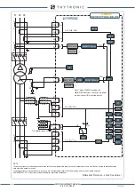
Note *: when 87NHIZ is enabled, the
50N/51N/67N functions can not be used with
residual current (IE) measured directly
Differential Protection - Motor
NOTE
Incoming currents must be connected to relay reference amperometric input terminals; outgoing currents must be connected to protection relay
amperometric output terminals.
Incoming currents in relay reference terminals are considered positive, while the outgoing ones are considered negative.
CONVENTION - CT’s P1 polarity is indicated towards protected component.
Z1
Z2
Z3
Z4
Z5
Z6
XMR-D EQUIPMENT MANUAL
Ed. 2.9 - 02/2021


