


FUNCTION CHARACTERISTICS
233
—
Rotor Earth Fault - 64F
Preface
Rotor earth fault (64F)
The field circuit has no ground connections, whereby the generator may continue operation even
with a first ground fault. A ground fault however, increases the probability of a second ground fault
somewhere else, with which there would be unbalances in the rotor flux, with consequent vibrations
in the bearings and the shaft of the machine. A rotor ground protective element is available, having
the aim of anticipating damage to the generator by detecting the first earth fault in the field circuit.
Such protection may be used on alternator excitation circuits with capacitance to ground of up to
2
m
F and static exciters having nominal voltages up to 660 Vdc. Measurement uses a 50 Hz signal
applied to the generator field circuit.
There is no circulation of any current due to the application of the 50 Hz signal until the field circuit
loses insulation. Instead, in the case of the first ground fault, there is the circulation of a current at
50 Hz, which the XMR measures as the sole resistive component in order to determine the resistance
of the circuit insulation to ground, calculated as the ratio between the voltage applied at 50 Hz and
the corresponding resistive component of the current.
The reduction in the resistance measured by the relay indicates a first loss of field circuit insulation.
The relay must be connected to both positive and negative poles of the field circuit with the aim of
reducing the influence of harmonics in the measurement; in the case of inaccessibility to one of the
two poles, then connection may in any case be made to the sole accessible pole. An appropriate
filter allows attenuation of the harmonics generated by the static exciters to 150 and 300 Hz.
The filter for attenuation of the harmonics and the coupling resistances for the field circuit are hou-
sed within the same casing of XMR relay. To generate the voltage applied to the circuit field a sepa-
rate input auxiliary power at 50 Hz is available, regardless of XMR auxiliary input voltage.
The measured insulation resistance is compared with two adjustable thresholds, the first scheduled
for alarm (
R
FAL
<) and the second for tripping (
R
F
<<); in addition, each threshold is independently
delayed (
t
RFAL
<,
t
RF
<<).
Tripping of the second threshold inhibits the first alarm threshold.
Each of the two thresholds may be associated with the breaker fault (BF) function.
The logical block for each of the two thresholds may be programmed from a binary input.
Operation and settings
A 50 Hz or 60 Hz voltage
U
F
is applied in the field circuit of the alternator and a ground; in the absen-
ce of earth fault (
R
F
=
∞
) only a few mA current is established in the circuit through the capacities
between the field circuit and the earth.
In case of earth fault, the current increases in inverse proportion to the value of fault resistance.
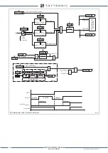
With reference to the simplified diagram shown in the drawing, by calculating the ratio
U
F
/
I
RF
is
obtained by measuring the insulation resistance to ground
R
F
circuit excitation.
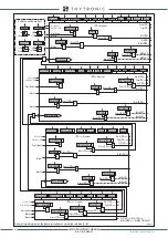
Based on the measured values (Vmis and Imis) protection calculates the resistive component of
current:
I
RF
=
I
F
·
cos
ϕ
=
U
F
/
R
F
so:
R
F
=
U
F
/(
I
F
·
cos
ϕ
)
Cri-64F.ai
Injection
supply
Vmis
C
R
R
F
U
F
Imis
Field
winding
G
R
F
<
Cri1-64F.ai
Injection
supply
Vmis
C
R
I
C
I
RF
I
F
U
F
U
F
R
F
Imis
Field
winding
G
~
I
RF
ϕ
I
C
I
F
XMR-D EQUIPMENT MANUAL
Ed. 2.9 - 02/2021


